4.4 ESB Bus Interface Module
ESB bus interface module (Model: SSB401) is installed in the safety node unit for communi-
cating with the ESB bus coupler module (Model: SEC402/SEC401) installed in the safety con-
trol unit. The ESB bus interface module is always dual-redundantly configured.
n
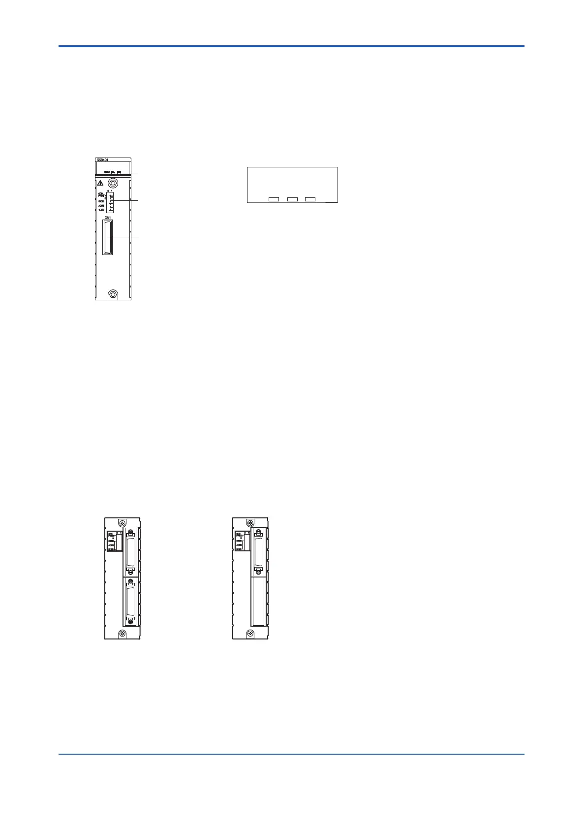
Configuration
RSP SEL STATUS
LED display close-up
ESB bus address setting
DIP switch
LED display
ESB bus connector
Figure 4.4-1 SSB401
l
LED Display
•
STATUS: This LED turns on when the self-diagnosis has been completed normally and
the ESB interface is operating normally, otherwise it is turned off.
• SEL: This LED flashes during data transmission to an I/O module, otherwise it is off.
• RSP: This LED flashes during data reception from an I/O module, otherwise it is off.
l
ESB Bus Connector
The ESB bus connector is connected to a connector unit for ESB bus, (shown in the following
figure), via an ESB bus cable (YCB301).
Connect the ESB bus cable connector to a connector unit with terminator for ESB bus to ter-
minate the ESB bus.
Connector unit
for ESB bus
Connector unit with
terminator for ESB bus
Figure 4.4-2 Connector Unit for ESB Bus and Connector Unit with Terminator for ESB Bus
<4.4 ESB Bus Interface Module > 4-15
IM 32Q06C10-31E 4th Edition : Jan.30,2015-00
 Loading...
