5.3 Signal Cable Connection to Analog Input/
Output Modules
This section contains the wire connection diagrams and tables showing the I/O channel num-
bers.
There are three ways of connecting input signal cables to analog I/O modules: by connecting
via a pressure clamp terminal block, by using a signal cable to connect to the connectors via
a terminal board, or by direct connection using a MIL cable.
The following table shows the relationship between the analog input/output module and the
field wiring connection methods.
Table 5.3-1 Analog Input/Output Module and Field Wiring Connection Methods
Analog input/output
module (type)
Field wiring connection methods (*1)
Pressure clamp terminal Terminal board MIL cable
SAI143 Yes Yes Yes
SAV144 Yes Yes Yes
SAT145 - Yes -
SAR145 - Yes -
SAI533 Yes Yes Yes
*1: Yes: Connection possible
n
T
erminal Numbers and Pin Numbers
l
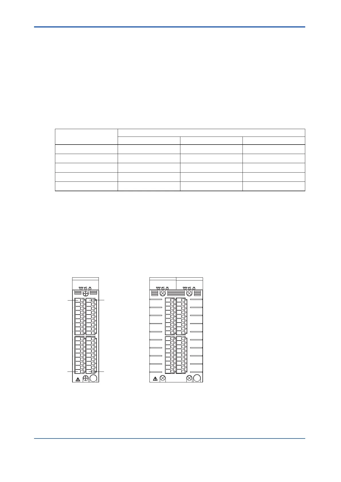
Pressure Clamp Terminal Blocks
The terminal numbers of a pressure clamp terminal block are arranged in the order from A1,
A2 and so on to A18 starting from the top of the left column and from B1, B2 and so on to B18
from the top of the right column on the front of the terminal block.
The terminal number layout of a dual-redundant type pressure clamp terminal is the same.
For single operation
For dual-redundant operation
Same pin numbers as
for single operation
A1
A18
B1
B18
Figure 5.3-1 Terminal Numbers of Pressure Clamp Terminal Blocks
<5.3 Signal Cable Connection to Analog Input/Output Modules > 5-14
IM 32Q06C10-31E 4th Edition : Jan.30,2015-00
 Loading...
