2.1 Installing Rack Mountable Devices
This chapter explains the procedure for installing the safety control unit, the safety node unit,
and the unit for the optical ESB bus repeater module, on a 19-inch rack.
SEE
ALSO
For more information about installation of ProSafe-RS hardware, refer to:
ProSafe-RS Installation Guidance (TI 32S01J10-01E)
n
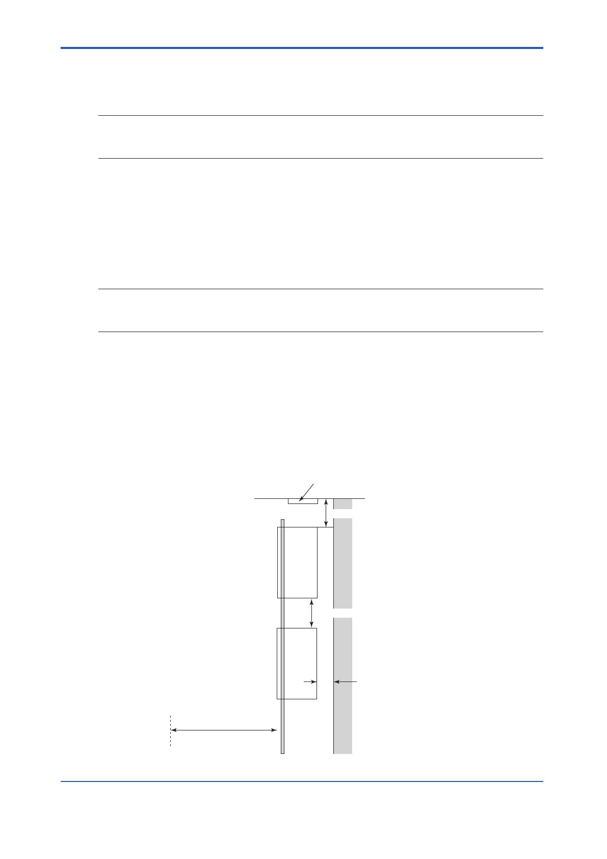
Space for Heat Radiation
The suf
ficient spaces for heat radiation should be reserved.
• When a safety control unit, a safety node unit, and a unit for optical bus repeater module
are installed on the same rack, they should be placed away from each other at least for 3
UNIT (1 UNIT=44.45mm).
• If the repeaters and other devices are installed on the same rack, they should be placed
away from each other at least for 3 UNIT (1 UNIT=44.45mm).
SEE
ALSO
For more information about equipment installation environment, refer to:
ProSafe-RS Installation Guidance (TI 32S01J10-01E)
n
Maintenance Spaces
Be sure to allow spaces for maintenance.
•
All cables for units and I/O modules are connected to the front.
• The indicator lamp checks, setting, inspection, removal, and insertion of each module or
unit are done from the front of the equipment.
• Adequate space is required for suction and exhaust of the cooling fan of equipment.
• Allow a space of at least 1000 mm in front of the equipment for wiring and maintenance.
Top panel
Front
Maintenance area
Min. 3 UNIT
Min. 50 mm
Min. 100 mm
Min. 1000 mm
Do not stack instruments without space.
Fan
Figure 2.1-1 Rack Mounting Space
<2.1 Installing Rack Mountable Devices> 2-2
IM 32Q06C10-31E 4th Edition : Jan.30,2015-00
 Loading...
