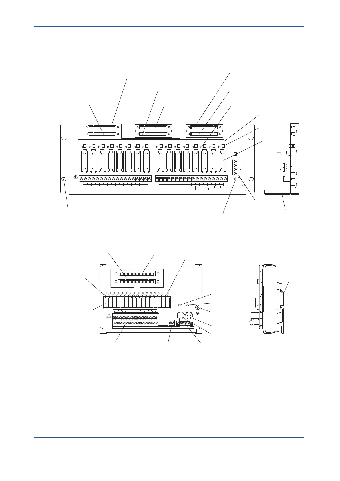
8.2 Names of Parts
The following figure shows the names of the parts on the relay board. If you are not using a
connector to connect to a digital input/output module, install the connector cover
.
CN1
CN2
CN3
CN4
CN5
CN6
TM1
FUSE
1 2 3 4 5 6 7 8 9 10 11 12 13 14 15 16
TM2
TM3
24V
DC
+
Holes for mounting rack
(4 holes; M5 screws)
Fuse
Operation Indication Lamp
Relay
Field Terminal (TM1)
Field Terminal (TM2)
Cable Tray
Digital Output Module
Connector
Digital Output Module
Connector
Relay Number
Digital Output Module
Connector (Redundant)
Digital Output Module
Connector (Redundant)
Digital Input Module
Connector
Digital Input Module
Connector (Redundant)
Relay Power Supply
Terminals
Grounding Terminal
Figure 8.2-1 Parts and Names on the 19-Inch Rack Mountable Relay Board (SRM53D)
CN1
CN2
POWER1 POWER2
FUSE1
250V T 10A
FUSE2
250V T 10A
READY
1A
1 2 3 4 5 6 7 8 9 10 11 12 13 14 15 16
2A 3A 4A 5A 6A 7A 8A
1B 2B 3B 4B 5B 6B 7B 8B
9A 10A 11A 12A 13A 14A 15A 16A
9B 10B 11B 12B 13B 14B 15B 16B
DIN rail
Digital Output Module
Connector (Redundant)
Operation Indication
Lamp Relay
Digital Output Module
Connector
Relay Number
LED for power1
LED for power2
Fuse for power2
Fuse for power1
Grounding
Terminal
Field Terminals
Relay
Ready Terminals Relay Power Supply Terminals
Figure 8.2-2 Parts and Names on the DIN Rail Mountable Relay Board (SBM54D)
<8.2 Names of Parts > 8-3
IM 32Q06C10-31E 4th Edition : Jan.30,2015-00
 Loading...
