5.4.4 Connection with a Terminal Board (Digital Input/
Output Module)
The following table shows the relationship between digital input/output modules and terminal
boards.
Table 5.4.4-1 Relationship Between Terminal Boards and Digital Input/Output Modules
Terminal board (type) Connectable digital input/output module (type)
SED2D SDV521
SED3D SDV53A
SED4D SDV144, SDV531, SDV541
SWD2D SDV526
SBD2D SDV521
SBD3D SDV531, SDV53A
SBD4D SDV144, SDV541
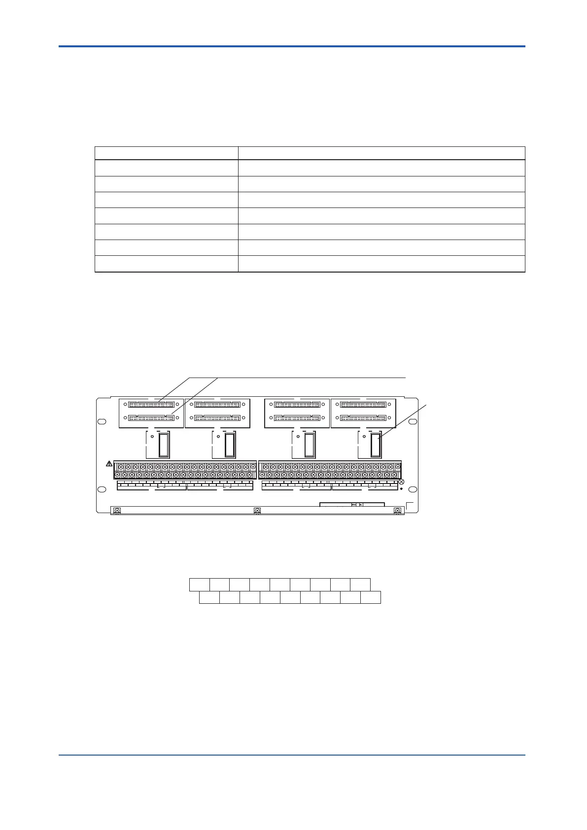
The following figure shows the relationship between the terminal numbers on each terminal
board and the signal names for the digital I/O modules that connect to the terminal board.
n
Connection Between SED2D and an Output Module
CN7
CN8
POWER
FUSE
R2
CN5
CN6
POWER
FUSE
R1
CN3
CN4
POWER
FUSE
L2
CN1
CN2
POWER
FUSE
L1
1A 2A 3A 4A NC + NC NC NC
1B 2B 3B 4B NC - NC NC NC
1A 2A 3A 4A NC + NC NC NC
1B 2B 3B 4B NC - NC NC NC
1A 2A 3A 4A NC + NC NC NC
1B 2B 3B 4B NC - NC NC NC
1A 2A 3A 4A NC + NC NC NC
1B 2B 3B 4B NC - NC NC NC
TM2
L2
TM3 TM4
R1 R2
TM1
L1
Connect to both the CN1 and CN2, the CN3 and CN4,
the CN5 and CN6, or the CN7 and CN8 connectors
if the I/O modules are used in a dual-redundant configuration.
Fuses (15A 4 Pieces)
Figure 5.4.4-1 SED2D Terminal Board
l
When Connecting SDV521 (24 V DC Power Supply Required)
Signal Name
Signal Name
TM1, TM2, TM3, TM4
Terminal No.
1A 2A 3A
4A
OUT1 OUT2 OUT3 OUT4 N.C. + N.C. N.C. N.C.
COM1 COM2 COM3 COM4
N.C. – N.C. N.C. N.C.
1B 2B 3B 4B
N.C. : No Connection
Figure 5.4.4-2 SDV521 Signal Name and Terminal Number
<5.4 Signal Cable Connection to Digital Input/Output Modules > 5-28
IM 32Q06C10-31E 4th Edition : Jan.30,2015-00
 Loading...
