5.5.2 Connection of RS-422/RS-485 Communication
Module
Use an ALR121 serial communication module for RS-422/RS-485 communication. This sec-
tion explains the signal connections for this module.
n
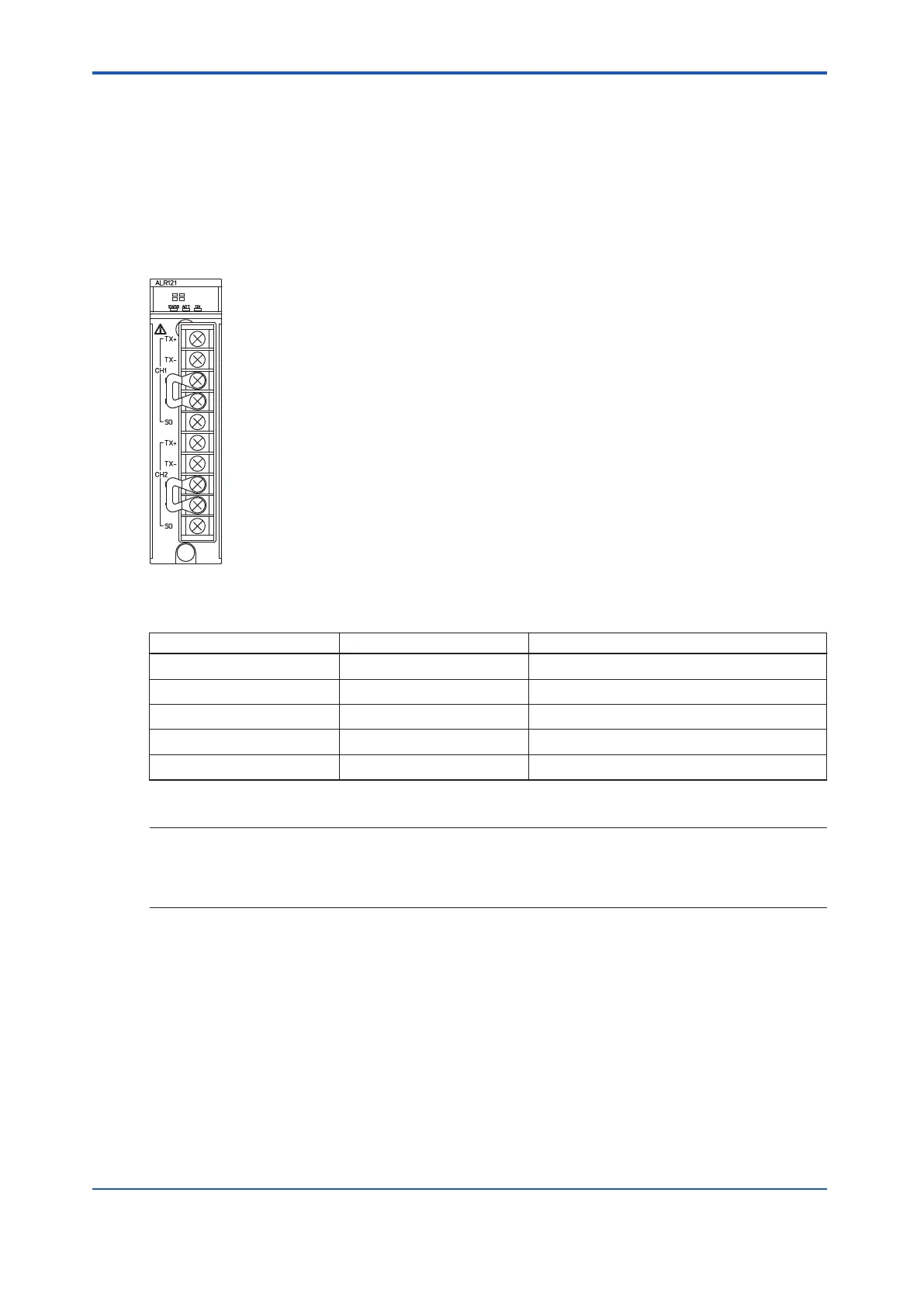
ALR121: RS-422/RS-485 Interface
The following figure shows the terminals on front panel of ALR121 module.
Figure 5.5.2-1 Terminal of Communication Module (ALR121)
Table 5.5.2-1 RS-422/RS485 Interface Terminal
Terminal name Signal name Remarks
TX+ Send Data Non-inverted
TX- Send Data Inverted
RX+ Receive Data Non-inverted
RX- Receive Data Inverted
SG Signal Ground -
Cable wring for an external device varies with the model of the device.
SEE
ALSO
For more information about connections for each external device model when connecting to the ALR121, re-
fer to:
The instruction manuals of the corresponding devices
n
ALR121 External Connection
When connecting the external device with ALR121, two methods for 1 to 1 and 1 to n (n: up to
32) are available. The following figure shows the configuration.
<5.5 Connection of Communication Modules > 5-41
IM 32Q06C10-31E 4th Edition : Jan.30,2015-00
 Loading...
