5.5.1 Connection of RS-232C Communication Module
Use an ALR1
11 serial communication module for RS-232C communication. This section ex-
plains the signal connections for this module.
n
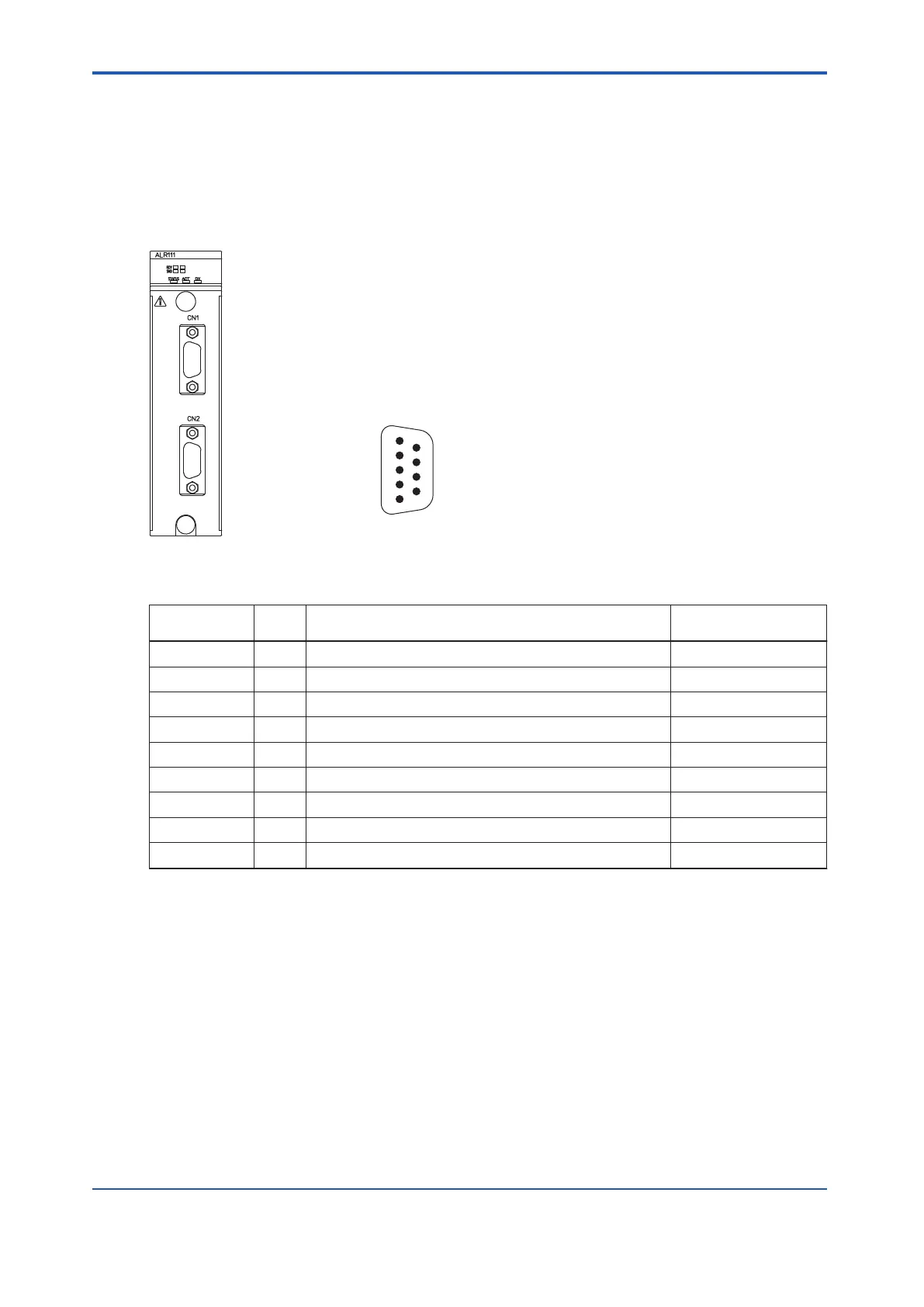
ALR111: RS-232C Interface
The connectors on ALR111 module are the 9-pin D-sub connectors.
5
4
3
2
1
9
8
7
6
Connector pin numbers on
D-sub 9 pin board side
Figure 5.5.1-1 ALR111 Communication Module and Connector Pin Numbers
Table 5.5.1-1 RS-232C Interface Connector Pin Position
CN1 and CN2
pin position
Ab-
brev
.
Signal name
Signal direction at
ALR111 side
1 CD Carrier Detect Input
2 RD Receive Data Input
3 SD Send Data Output
4 ER Equipment Ready Output
5 SG Signal Ground Signal ground
6 DR Dataset Ready Input
7 RS Request to Send Output
8 CS Clear to Send Input
9 - N.C. -
l
RS-232C Cable and Modem
Although the connection between the ALR1
11 module and an external device is recommen-
ded to go through the modems, if the distance between the two is less than 15 meters and
both the ALR111 module and the external device are sharing the same grounding levels, they
can be directly connected using a cable without modems.
n
Modbus Connection
The following types of Modbus connection are available:
• Connection with modem
• Connecting to an external device using an RS-232C D-sub 25-pin connector (direct con-
nection)
<5.5 Connection of Communication Modules > 5-35
IM 32Q06C10-31E 4th Edition : Jan.30,2015-00
 Loading...
