5.3.1 Analog Input Module, 16-Channel (SAI143)
A1IN1A
IN2A
IN3A
IN4A
IN5A
IN6A
IN7A
IN8A
IN9A
IN10A
IN11A
IN12A
IN13A
IN14A
IN15A
IN16A
N.C.
N.C.
IN1B
IN2B
IN3B
IN4B
IN5B
IN6B
IN7B
IN8B
IN9B
IN10B
IN11B
IN12B
IN13B
IN14B
IN15B
IN16B
N.C.
N.C.
CBSE (*1)
IN1A
IN2A
IN3A
IN4A
IN5A
IN6A
IN7A
IN8A
IN9A
IN10A
IN11A
IN12A
IN13A
IN14A
IN15A
IN16A
N.C.
N.C.
N.C.
N.C.
IN1B
IN2B
IN3B
IN4B
IN5B
IN6B
IN7B
IN8B
IN9B
IN10B
IN11B
IN12B
IN13B
IN14B
IN15B
IN16B
N.C.
N.C.
CBSE (*1)
CH1
Pressure clamp terminal
CH No. Signal Terminal No. Signal CH No. Signal Pin No. Signal
CH2
A2
A3
A4
A5
A6
A7
A8
A9
A10
A11
A12
A13
A14
A15
A16
A17
A18
B1
B2
B3
B4
B5
B6
B7
B8
B9
B10
B11
B12
B13
B14
B15
B16
B17
B18
N.C.: No Connection
CH15
CH16
*1: Short circuit CBSE externally for MIL connectors
in order to detect unconnected external cables.
40
CH1
MIL connector
CH2
38
36
34
32
30
28
26
24
22
20
18
16
14
12
10
8
6
39
37
35
33
31
29
27
25
23
21
19
17
15
13
11
9
7
5
CH15
CH16
4
2
3
1
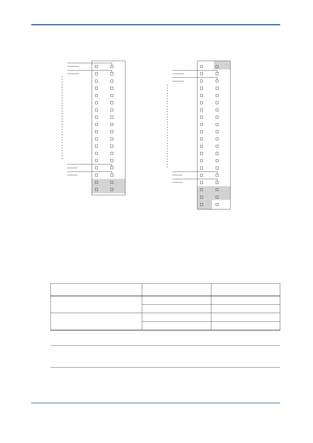
Figure 5.3.1-1 SAI143 External Connection
n
Cable Connection of SAI143 Analog Input Module
Cable connection of SAI143 analog input module varies with the pin settings and input termi-
nals shown as follows.
Table 5.3.1-1 SAI143 Analog Input Module Pin Settings and Input Terminals
SAI143 Setting
Signal
("n" is channel number)
Signal and Polarization
Pin Setting: 2-Wire(*1)
INnA 2-wire transmitter input +
INnB 2-wire transmitter input -
Pin Setting: 4-Wire(*1)
INnA Current input -
INnB Current input +
*1: When power failure or other abnormality occurs in SAI143, the current input loop becomes open. Thus, the current input sig-
nal should not be connected in parallel with other device.
SEE
ALSO
For more information about analog input/output module circuit diagrams, refer to:
“n Analog Input/Output Modules” on page 5-47
<5.3 Signal Cable Connection to Analog Input/Output Modules > 5-16
IM 32Q06C10-31E 4th Edition : Jan.30,2015-00
 Loading...
