5.4 Signal Cable Connection to Digital Input/
Output Modules
This section contains wire connection diagrams and tables with the I/O channel numbers.
There are three ways of connecting input signal cables to digital I/O modules: by connecting
via a pressure clamp terminal block, by using a signal cable to connect to the connectors via
a terminal board, or by direct connection using a MIL cable.
The following table shows the relationship between the digital input/output module and the
field wiring connection methods.
Table 5.4-1 Digital Input/Output Module and Field Wiring Connection Methods
Digital input/output
module
Field wiring connection methods (*1)
Pressure clamp terminal Terminal board MIL cable
SDV144 Yes Yes Yes
SDV521 - Yes -
SDV526 - Yes -
SDV531-S/SDV531-L Yes Yes Yes
SDV53A - Yes -
SDV541 Yes Yes Yes
*1: Yes: connection possible
n
T
erminal Numbers and Pin Numbers
l
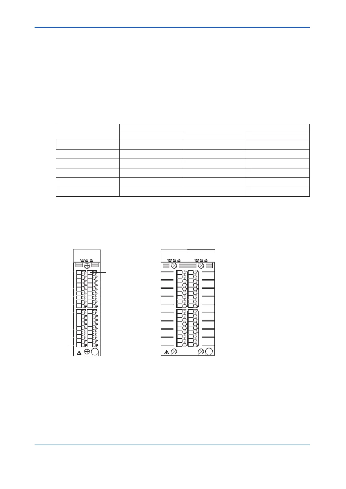
Pressure Clamp Terminal Block
For single operation
For dual-redundant operation
Same pin numbers as
for single operation
A1
A18
B1
B18
Figure 5.4-1 Terminal Number of Pressure Clamp Terminal Block
l
MIL Connectors
MIL connectors for digital input/output have 50 pins.
<5.4 Signal Cable Connection to Digital Input/Output Modules > 5-22
IM 32Q06C10-31E 4th Edition : Jan.30,2015-00
 Loading...
