4.2 Processor Module
Control algorithm calculations are performed in the processor modules.
Three types of processor modules are available: one for V net (Model: SCP401) and the other
for Vnet/IP (Model: SCP461/SCP451) .
n
Configuration
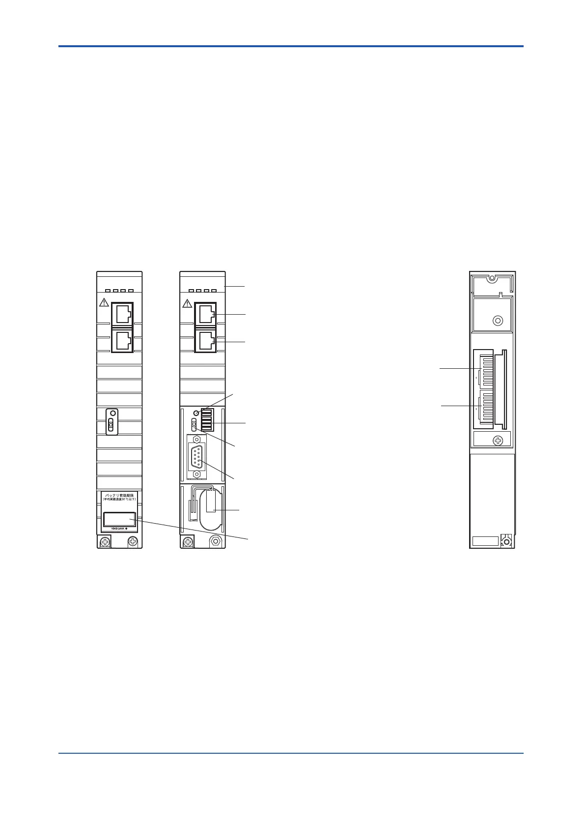
The following diagram shows the front and rear views of processor module.
The batteries are installed behind the front cover
.
The DIP switches for setting domain number and station numbers are placed at the rear part
of the processor module. When setting the DIP switches, it is necessary to remove the pro-
cessor module from the safety control unit.
l
SCP401
RCV 1 2
SND 1 2
1 2 3 4 5 6 7 8
HRDY
RDY
CTRL COPY
BUS1
BUS2
START
/STOP
START
/STOP
BATTERY
BATTERY
ON
OFF
PORT
DOM
ST A
CN1
RCV 1 2
SND 1 2
1 2 3 4 5 6 7 8
HRDY
RDY
CTRL COPY
BUS1
BUS2
ON
OFF
1
0
P
BATTERY LIFE
(AVE.ROOM TEMP 30°C MAX.)
ON
OFF
DOMAIN NO. STATION NO.
0 0
MSB LSB
P MSB LSB
SCP401
SYNC
SCTY
SYNC
SCTY
SCP401
CN2
START/STOP switch
Maintenance connector
V net connector
Bus 1
V net connector
Bus 2
Battery
LED display
Battery ON/OFF switch
Battery expiration date label
Front setting switch
(6-bit DIP switch)
Station address setting switch
For domain number
For station number
Rear Front
Behind front cover
Figure 4.2-1 SCP401 Overview
<4.2 Processor Module > 4-3
IM 32Q06C10-31E 4th Edition : Jan.30,2015-00
 Loading...
