n
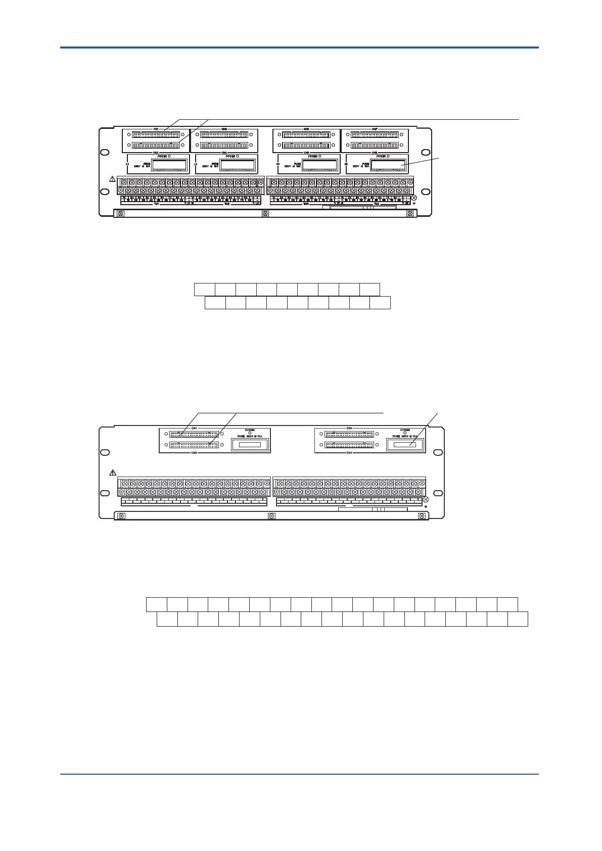
Connection Between SED3D and an Output Module
Connect to both the CN1 and CN2, the CN3 and CN4, the CN5 and CN6,
or the CN7 and CN8 connectors if the I/O modules are used in a dual-redundant configuration.
Fuses (10A 4 Pieces)
Figure 5.4.4-3 SED3D Terminal Board
l
When Connecting SDV53A (48 V DC Power Supply Required)
Signal Name
Signal Name
TM1, TM2, TM3, TM4
Terminal No.
48 V DC
1A 2A 3A
4A
1B 2B 3B 4B
5A 6A 7A
8A
5B 6B 7B 8B
+
–
COM1 COM2 COM3 COM4 COM5 COM6 COM7 COM8 COM
OUT1 OUT2 OUT3 OUT4 OUT5 OUT6 OUT7 OUT8
Figure 5.4.4-4 SDV53A Signal Name and Terminal Number
n
Connection Between SED4D and an Input/Output Module
TM1 TM2
Connect to both the CN1 and CN2,
or the CN3 and CN4 connectors if the I/O modules
are used in a dual-redundant configuration.
Fuses (10A 2 Pieces)
Figure 5.4.4-5 SED4D Terminal Board
l
When Connecting SDV144 (V
oltage-free Contact Input) (24 V DC power
supply required)
1A 2A 3A 4A 5A 6A 7A 8A 9A 10A 11A 12A 13A 14A 15A 16A 17A +
DC10 DC11DC8 DC9 DC12 DC13 DC14 DC15 DC16DC1 DC2 DC3 DC4 DC5 DC6 DC7
1B
Signal Name
Signal Name
TM1, TM2
Terminal No.
2B 3B 4B 5B 6B 7B 8B 9B 10B 11B 12B
13B 14B 15B 16B 17B -
24 VDC
COM
N.C.
N.C.
IN10 IN11IN8 IN9 IN12 IN13 IN14 IN15 IN16IN1 IN2 IN3 IN4 IN5 IN6 IN7
N.C. : No Connection
Figure 5.4.4-6 SDV144 Signal Name and Terminal Number
<5.4 Signal Cable Connection to Digital Input/Output Modules > 5-29
IM 32Q06C10-31E 4th Edition : Jan.30,2015-00
 Loading...
