SEE
ALSO
For more information about settings on I/O Parameter Builder, refer to:
A4.6, “Items set for discrete inputs” in Safety Control Station Reference (IM 32Q03B10-31E)
n
Connecting the SBM54D to a Digital I/O Module
The following table shows the relations of the digital I/O modules connector numbers and the
connected field terminal numbers.
Table 8.3.1-7 Connector Numbers and Connected Field Terminal Numbers
Connector num-
ber
Connection Field terminal number Remarks
CN1
SDV541 1 to 16 CN1/CN2 redundancy
CN2
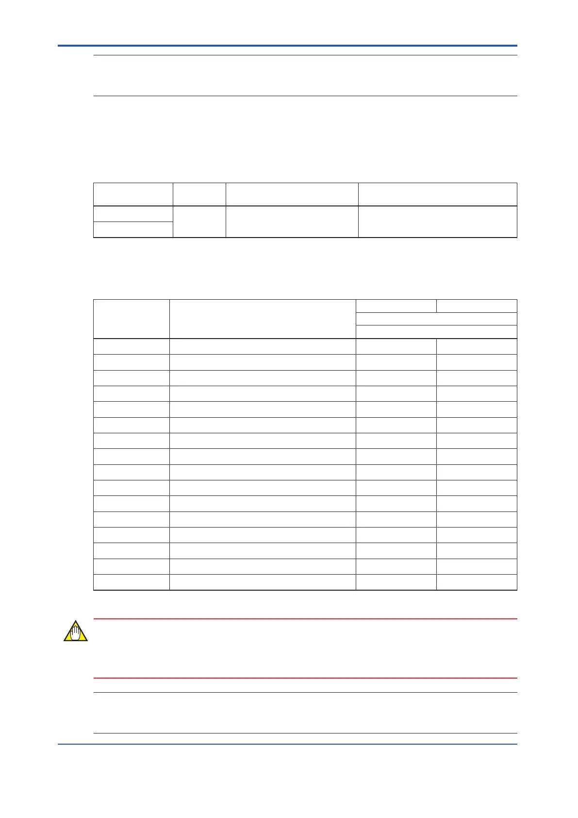
The following table shows the relations among the relay numbers, the field terminals, the digi-
tal output module connectors, and the SDV541/SDV144 channel numbers.
Table 8.3.1-8 Relay Numbers/Field Terminals/Channel Numbers
Relay number
(*1
)
Field terminal
CN1 CN2
SDV541 channel number
SDV541
1 1A/1B ch1 ch1
2 2A/2B ch2 ch2
3 3A/3B ch3 ch3
4 4A/4B ch4 ch4
5 5A/5B ch5 ch5
6 6A/6B ch6 ch6
7 7A/7B ch7 ch7
8 8A/8B ch8 ch8
9 9A/9B ch9 ch9
10 10A/10B ch10 ch10
11 11A/11B ch11 ch11
12 12A/12B ch12 ch12
13 13A/13B ch13 ch13
14 14A/14B ch14 ch14
15 15A/15B ch15 ch15
16 16A/16B ch16 ch16
*1: The relay number is the number printed on the SRM54D metal body above each relay.
When SDV541 is connected to SBM54D, Detect Disconnection, Pulse Test (OFF) and Pulse
T
est (ON) should be disabled on I/O Parameter Builder.
SEE
ALSO
For more information about settings on I/O Parameter Builder, refer to:
A4.7, “Items set for discrete outputs” in Safety Control Station Reference (IM 32Q03B10-31E)
<8.3 Cable Connection > 8-9
IM 32Q06C10-31E 4th Edition : Jan.30,2015-00
 Loading...
