The internal cooling circuit 115
Additional US and Canada requirements
To comply with the requirements of UL508C, install a pressure relief valve in the liquid
cooling unit. The recommended discharge rate of the valve is 8…10 bar (800…1000 kPa).
Coolant temperature control
The temperature of the coolant in the internal cooling circuit must be kept within the limits
specified in Specifications on page 117. Note that the minimum temperature is dependent
on ambient temperature and relative humidity.
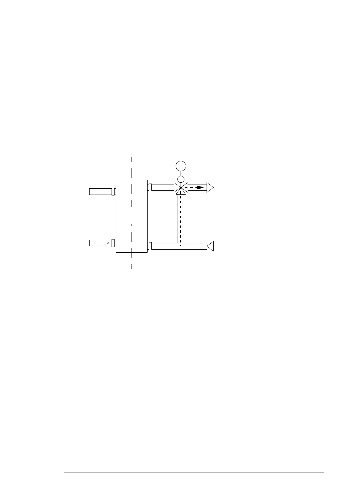
The following diagram shows an example of coolant temperature control using the three-
way valve in the external cooling circuit. Part of the infeed coolant flow is directed into the
return pipe through a three-way valve without letting it circulate in heat exchanger if the
coolant in the internal circuit is too cold.
Mechanical installation
Coupling the internal cooling circuit to a customer cooling unit
Connect the external cooling circuit directly to the coupling pipes on the side of the
converter. Lay liquid piping with extreme care. Secure the pipes properly mechanically and
check for leaks.
Infeed
Bypass valve
TC
Return
External circuitInternal circuit
Heat
exchanger
 Loading...


