38 Operation principle and hardware description
Auxiliary Measuring Unit NAMU-01C
Auxiliary Measuring Unit NAMU-01C is connected to CH2 of the RDCO module.
Connectors of the unit are shown below.
Fiber optic links
Grid-side converter: DDCS fiber optic links are provided by RDCO modules (installed on
the RDCU control units) for PC tools, master/follower link, NDIO, NTAC, NAIO, AIMA I/O
module adapter and fieldbus adapter modules of type Nxxx. For the connections, see
RDCO user’s manual [3AFE64492209 (English)].
Rotor-side converter: DDCS fiber optic links are provided by NDCU control unit for PC
tools, master/follower link, NDIO, NTAC, NAIO, AIMA I/O module adapter and fieldbus
adapter modules of type Nxxx.
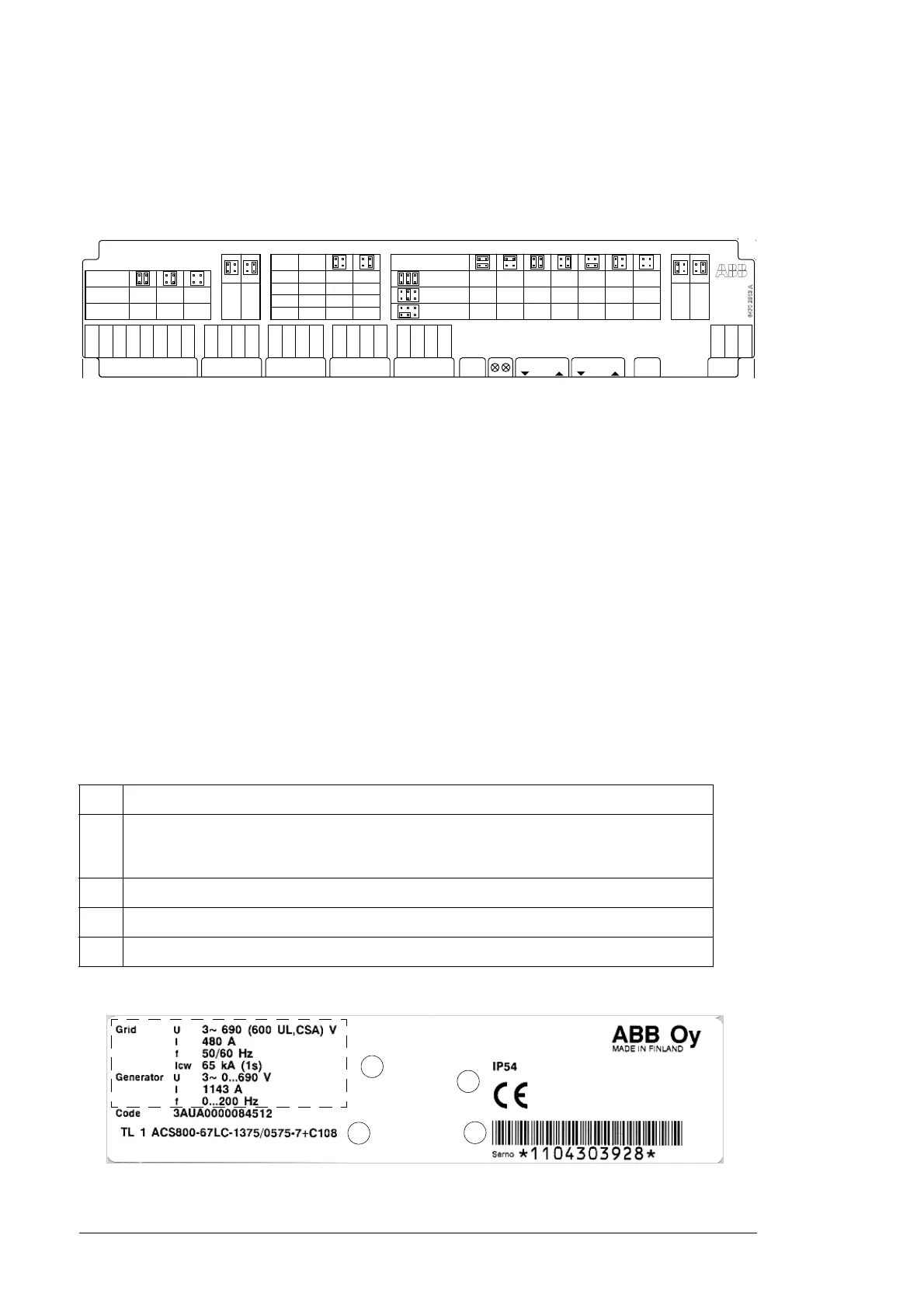
Type designation labels
Type designation label is attached to the door of the ACU cubicle (inside and outside of the
door). The type designation label includes ratings, valid markings, type code and serial
number of the unit. Each power module is also individually labeled.
Example label is shown below.
No. Description
1 Serial number. The first digit of the serial number refers to the manufacturing plant. The next
four digits refer to the unit’s manufacturing year and week, respectively. The remaining digits
complete the serial number so that there are no two units with the same number.
2 Type code. See section Type designation key.
3 Valid markings
4 Ratings of the unit
D D C S
[ 1 0 M B d ]
V 1 1 V 1 2
X 2 ( I U )X 1
1
2
3
4
X 3 ( I V ) X 4 ( I W ) X 5
5
6
7
8
1
2
3
4
D D C S
[ 5 M B d ]
S 1
D D C S
A D D R .
1 0 . . . 1 F
P W R O K
F A U L T
U V / D C -
X 6
1
2
3
S 2
2
1
6
5
± 3 , 7 3 8 ± 2 , 9 2 6 ± 2 , 0 9 0 ± 1 , 5 4 0 ± 1 , 0 2 7 ± 0 , 7 8 0 ± 0 , 6 8 8
± 0 , 9 3 4 ± 0 , 7 3 1 ± 0 , 5 2 2 ± 0 , 3 8 5 ± 0 , 2 5 7 ± 0 , 1 9 5 ± 0 , 1 7 2
± 0 , 4 6 7 ± 0 , 3 6 6 ± 0 , 2 6
1 ± 0 , 1 9 2 ± 0 , 1 2 8 ± 0 , 0 9 8 ± 0 , 0 8 6
2
1
6
5
2
1
6
5
8
7
1 0
9
8
7
1 0
9
8
7
1 0
9
8
7
1 0
9
8
7
1 0
9
8
7
1 0
9
8
7
1 0
9
2
1
4
3
2
1
4
3
C H 1
C H 2
C H 3
C H 4
I U
I V
I W
U D C
U 0
U U
U V
U W
X 3 1
X 3 2
X 3 3
X 3 4
A D C C H
C T
0 , 7
9
H A L L
2 , 8
9
H A L L
5 , 6
9
1 , 0 A
0 , 3 A
0 , 3 A
R M S
M A X
S E N S O R T Y P E A N D
S H U N T R E S I S T .
C H 2
T R A N S M I T T E R S E T T I N G
X 2 1 - X 2 4 C U R R E N T R A N G E B Y S E N S O R T Y P E A N D S H U N T R E S I S T A N C E
2
1
4
3
2
1
4
3
2
1
4
3
5 0 06 9 0 2 0 7
± 4 8 0± 6 8 7 ± 2 1 1
X 1 1 - X 1 4 V O L T A G E R A N G E A N D
X 1 5 M E A S U R I N G M O D E
P H A S E T O
P H A S E
P H A S E
P E A K R A N G E
X 3 1 - X 3 4 I / U S E L E C T I O N
U U
U W / D C +
+ 2 4 V
- 2 4 V
M / S 1
S 2
1
2
3
4
+ 2 4 V
- 2 4 V
M / S 1
S 2
1
2
3
4
+ 2 4 V
- 2 4 V
M / S 1
S 2
1
2
3
4
+ 2 4 V
- 2 4 V
0 V
0 V
S G N D
+ 2 4 V
0 V
0 = D I S A B L E D
1 = S H O R T
2 = M E D I U M
3 = L O N G
G N D
C H 1
V 2 1 V 2 2
C H 2
2
1
4
3
2
1
4
3
F L O A T I N G
M O D E
G R O U N D E D
M O D E
X 1 5
2
1
4
3
2
1
4
3
8 M B I T / S
S W
S E L E C T
X 8 D A T A R A T E
X 1 1 - X 1 4
N A M U - 0 1 C
A U X I L I A R Y M E A S U R I N G U N I T

 Loading...


