Operation principle and hardware description 29
Power modules
Size R8i modules are used in single or parallel configurations in both grid-side converter
and rotor-side converter. DC connection is located on the top front part of the module. The
DC voltage is connected to the busbars through fuses. Common mode filtering is
implemented by running the DC busbars through ferrite cores. Du/dt filtering is a standard
feature.
The generator connection is via a quick connector at the back of the module that couples
when the module is inserted into the cubicle. From the connector, the cables can be run
directly through the floor of the cubicle. Each parallel module is connected to the inverter
module cubicle internally by busbars.
The coolant enters the module at the bottom front and exits at the top. Inside the module,
the coolant runs through the heatsink as well as an air-to-liquid heat exchanger. For more
information on the liquid cooling system, see chapter The internal cooling circuit.
The cooling fan below the module forces air through the air-to-liquid heat exchanger and
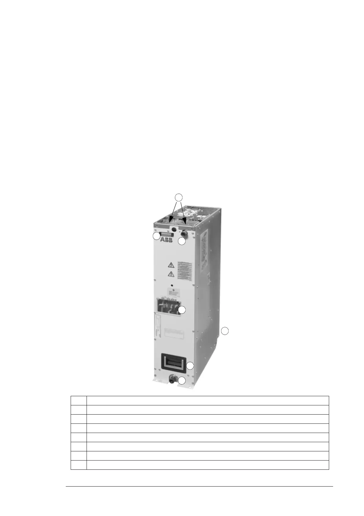
the module itself. The converter module is shown below.
3
2
4
No. Description
1 DC connections (UDC+ and UDC-)
2 Fiber optic connectors of the AINT board. Connected to the control units.
3 Terminal block X17 (not in use)
4 Handle
5 Coolant inlet connection
6 Coolant outlet connection
7 AC connections (U2,V2,W2). Quick connector for AC connection is located behind the module.
5
6
1
7

 Loading...


