Electrical installation 75
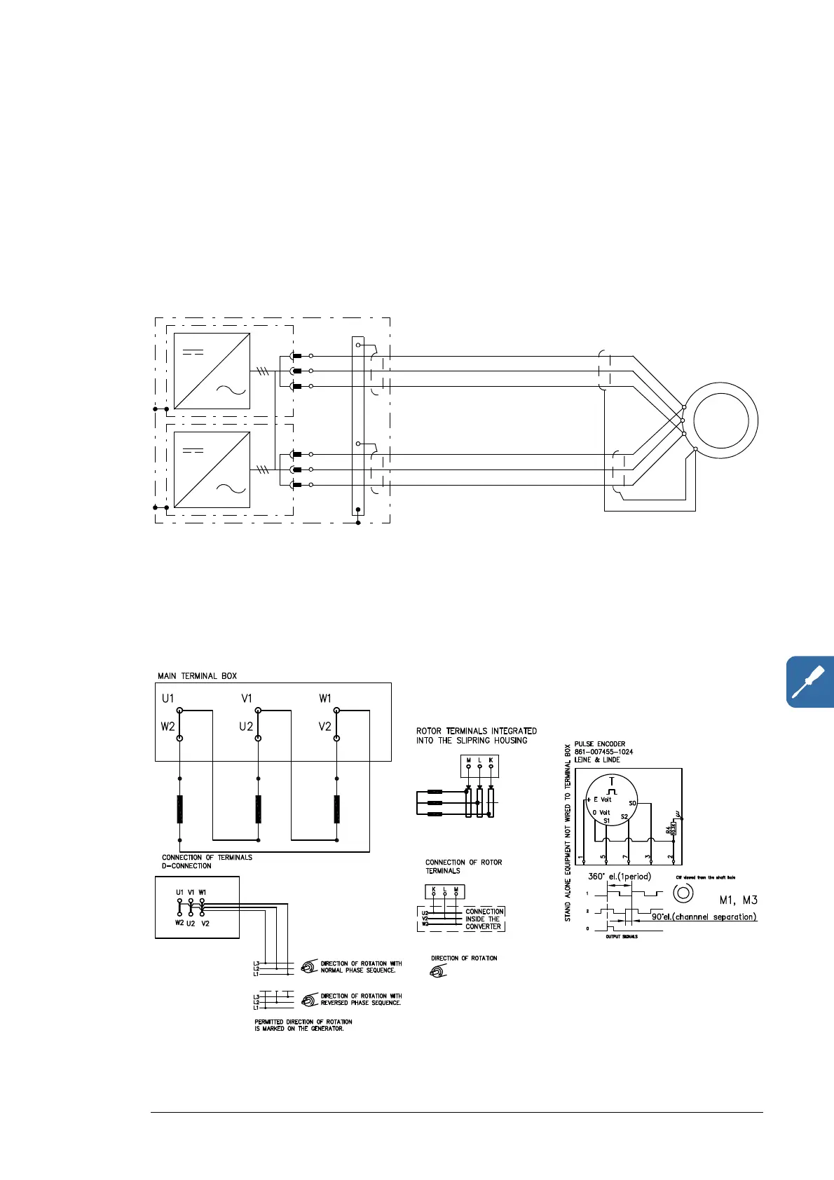
Connecting the rotor cables
Note: The cabling from all converter modules must be physically identical considering
cable type, cross-sectional area and length. When connecting several cables per phase, it
is recommended to divide the cables as evenly as possible among the modules.
Connection diagram
A connection diagram of frame 2×R8i parallel connected power modules feeding one
generator is shown below. The cable connection for frames 2×R8i and up is similar.
Note: Rotor-side cable connection terminals are U2, V2, W2 and PE. To be wired by the
user. For selection of the cables, see chapter Planning the electrical installation. For the
terminal sizes, tightening torques and lead-throughs, see chapter Technical data.
Note: Depending on the type of the generator used, the phase order may vary.

 Loading...


