46 Mechanical installation
Overview of the installation procedure
1. The cabinet can be installed with its back against a wall. Fasten the cabinet to the floor
with fastening clamps. For the location of the fastening clamps, see the delivery
specific dimensional drawings.
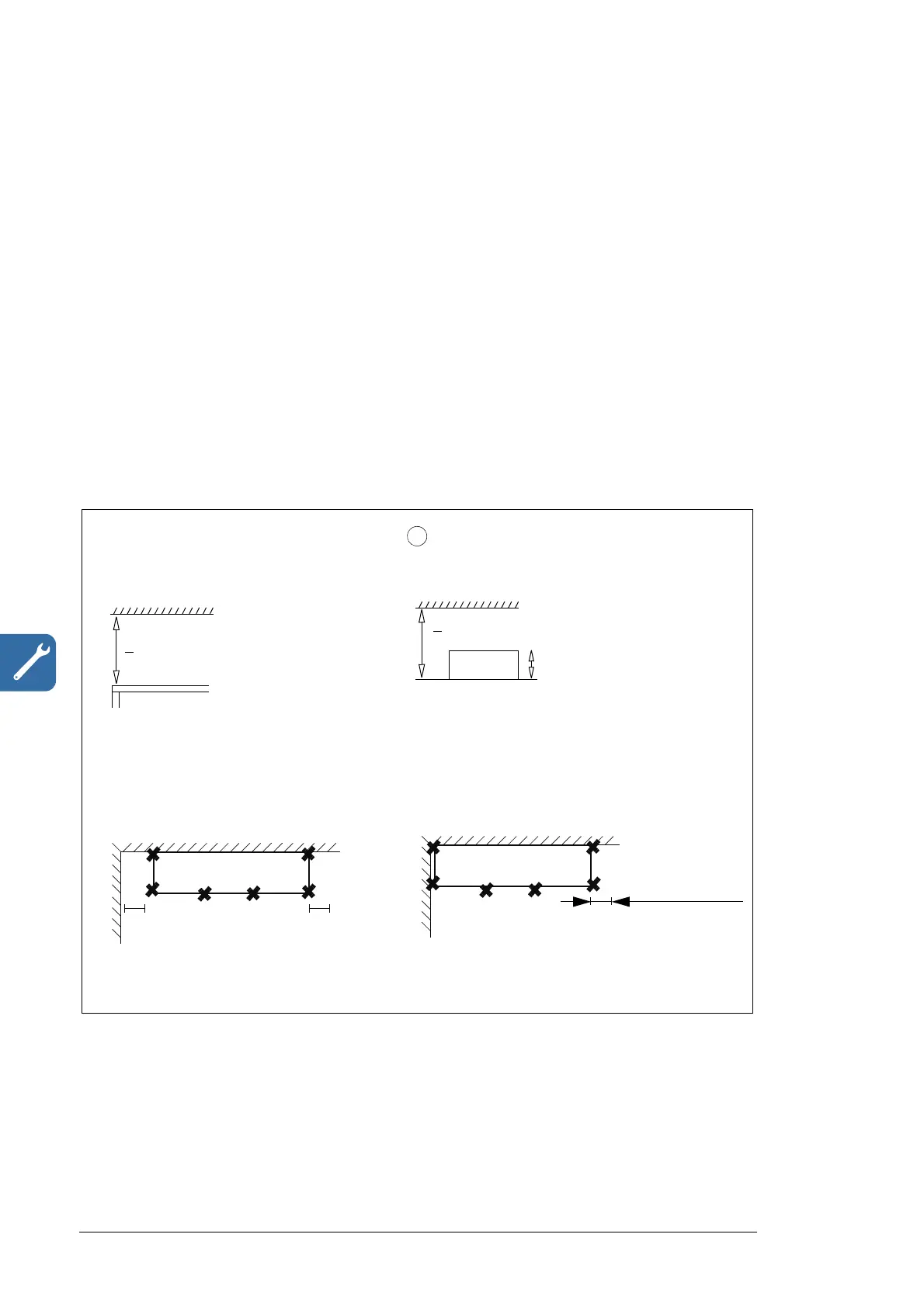
Note 1: Leave a minimum clearance of 400 mm above the basic roof level of the cabinet
to allow the pressure release lids to open at an arc fault.
Note 2: Leave some space at the side where the cabinet outmost hinges are to allow the
doors to open sufficiently. The doors must open 120° to allow converter module
replacement. For more accurate space requirements for the door openings, see chapter
Dimension drawings.
Note 3: Leave 115 mm free space at the right- or left-hand side of the converter for the
cooling pipe connections (depending on which side the cooling connections are).
Note 4: Leave 150 mm free space at the right-hand side for the plug-in connectors.
Note 5: Height adjustment can be done by using metal shims between the bottom frame
and floor.
1
150 mm (5.91 in.)
> 400 mm (15.75 in.)
Note 1: Top clearance
View from top
View from front
> 400 mm (15.75 in.)
d
Note 1: Top clearance
d = 80 mm (2.8 in.) when option +D150 is selected.
d = 170 mm (5.9 in.) when option +D150+D151 is
selected.
View from front (options +D150 and
+D151)
Note 4: Right-hand clearance
View from top
Note 2: Door opening clearance

 Loading...


