30 Operation principle and hardware description
Crowbar
The converter is equipped with active crowbar(s) as standard. The crowbar consists of
crowbar unit (type ACBU-Ax) and crowbar resistor (type ACBU-Rx).
The crowbar circuit is used for DC overvoltage protection in abnormal grid conditions, eg,
short interruptions or voltage dip/sag events. Active crowbar is needed when the converter
must stay connected to the grid during grid faults. The crowbar can be switched ON and
OFF by the rotor-side converter. This allows the converter to be connected to the grid even
during very severe grid faults.
Crowbar is triggered if the DC link voltage is too high or alternatively if the rotor current is
too high. Active crowbar is controlled by the rotor-side converter control program but in
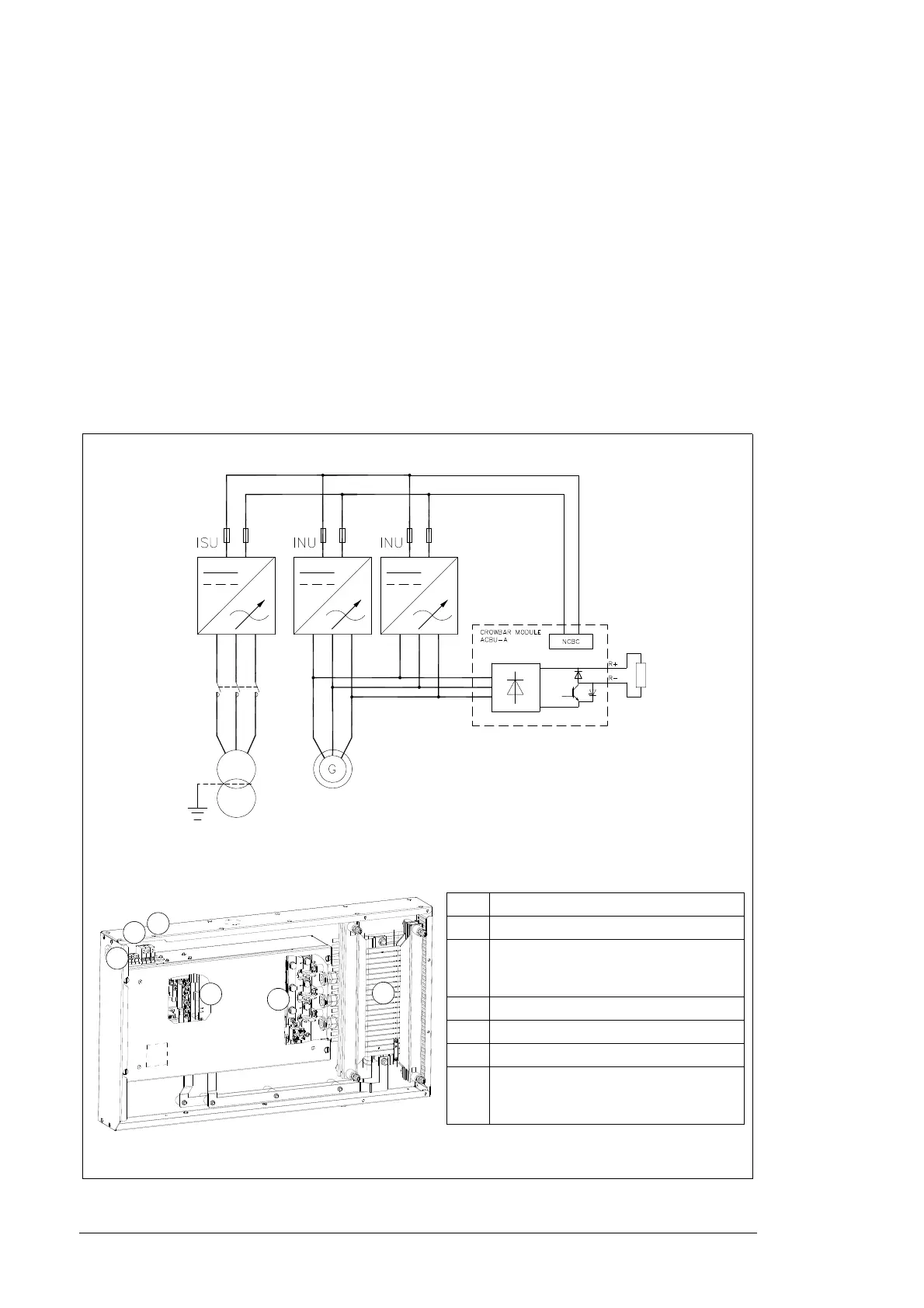
case of internal failure it can protect the converter independently. Circuit diagram and
layout of the crowbar is shown below.
Crowbar (ACBU-Ax)
x
No. Description
1 DC connections (UDC+ and UDC-)
2 Fiber optic connectors of the AITF
board (inside the cover). Connected to
the control units.
3 Terminal block (klixon)
4 Terminal block (triggered)
5 Crowbar resistor
6 AC connections (U2, V2, W2).
Connector for AC input connection is
located under the cover.
1
2
3
4
5
6

 Loading...


