54 Planning the electrical installation
Checking the compatibility of the generator and converter
For choosing the correct generator type, contact your local ABB representative.
Protecting the generator insulation and bearings
The rotor-side converter output consists of – regardless of output frequency – pulses of
approximately the converter DC link voltage with a very short rise time. The voltage of the
pulses can almost double at the generator terminals, depending on the attenuation and
reflection properties of the generator cables and terminals. This can cause additional
stress on the generator and generator cable insulation. Converters with fast rising voltage
pulses and high switching frequencies can cause current pulses that flow through the
generator bearings, and can gradually erode the bearing races and rolling elements.
The stress on generator insulation can be avoided by using ABB du/dt and common mode
filters. The converter is equipped with the following output filters as standard:
• du/dt filter that protects the generator insulation system and reduces bearing currents
• common mode filter that reduces bearing currents.
To avoid damage to the generator bearings, the cables must be selected and installed
according to the instructions given in this manual. In addition, insulated N-end (non-drive
end) bearings must be used.
Selecting the power cables
General rules
Dimension the grid-side and rotor-side connection cables according to local
regulations:
• The cable must be able to carry the converter load current and withstand the voltage
stress of the converter. See chapter Technical data for the rated currents.
• The cable must be rated for at least maximum permissible temperature of conductor in
continuous use. For US, see section Additional US requirements.
• The inductance and impedance of the PE conductor/cable (grounding wire) must be
rated according to permissible touch voltage appearing under fault conditions (so that
the fault point voltage will not rise excessively when a ground fault occurs).
• For 690 V AC rated equipment, the rated voltage between the conductors of the cable
should be minimum 1 kV.
For generators, symmetrical shielded generator cable is recommended.
A four-conductor system is allowed for grid-side cabling, but shielded symmetrical cable is
recommended.
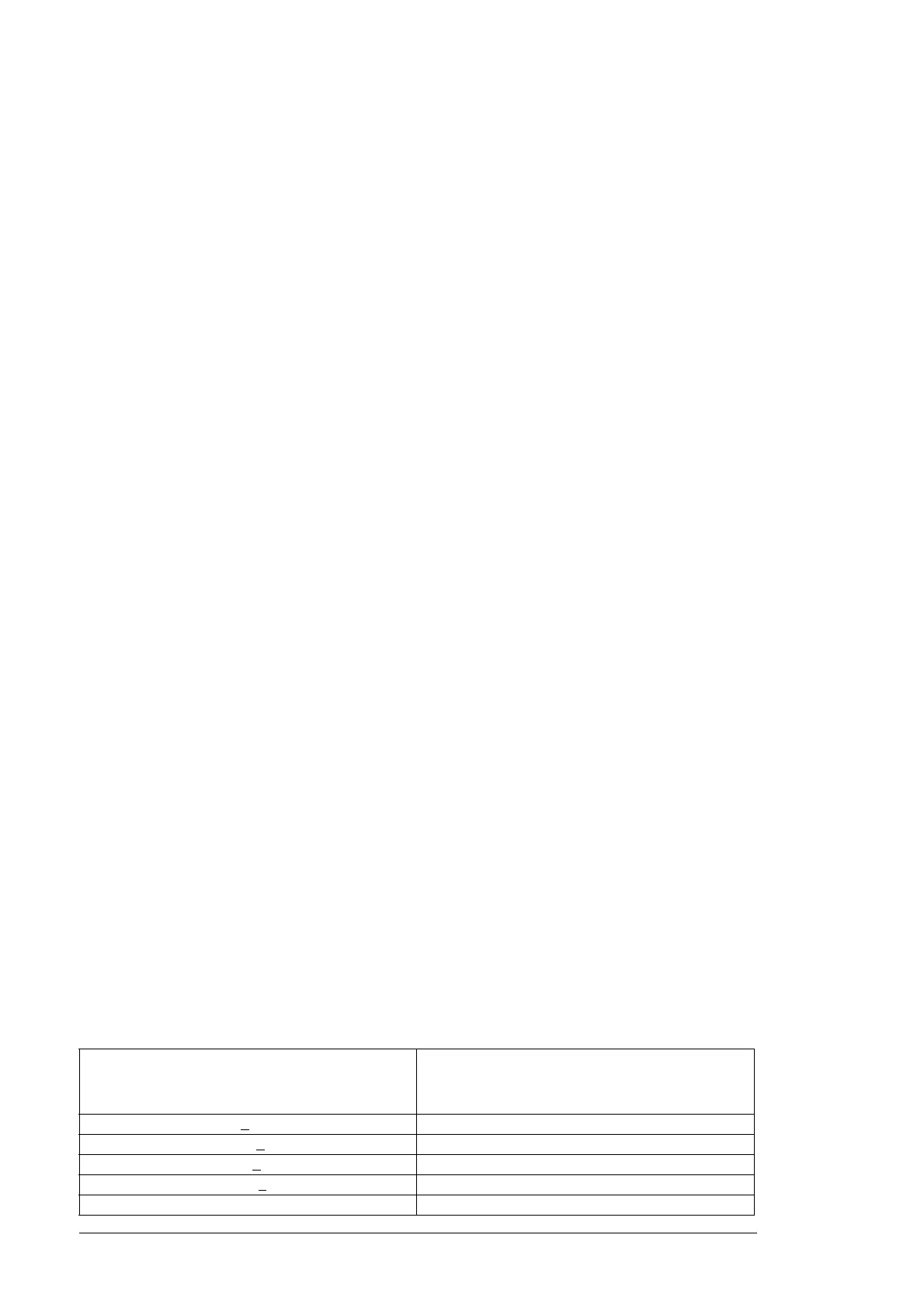
To operate as a protective conductor, the shield conductivity requirements according to
IEC 61800-5-1 are shown below when the protective conductor is made of the same metal
as the phase conductors. The table applies also to four conductor systems.
Cross-sectional area of the phase conductors
S (mm
2
)
Minimum cross-sectional area of the
corresponding protective conductor
S
p
(mm
2
)
S <
16 S
16 < S <
35 16
35 < S <
400 S/2
400 < S < 800 200
800 < S S/4

 Loading...


