Home
ABB
Media Converter
ACS800-67LC
ABB ACS800-67LC User Manual
4
of 1
of 1 rating
154 pages
Give review
Manual
Specs
To Next Page
To Next Page
To Previous Page
To Previous Page
Loading...
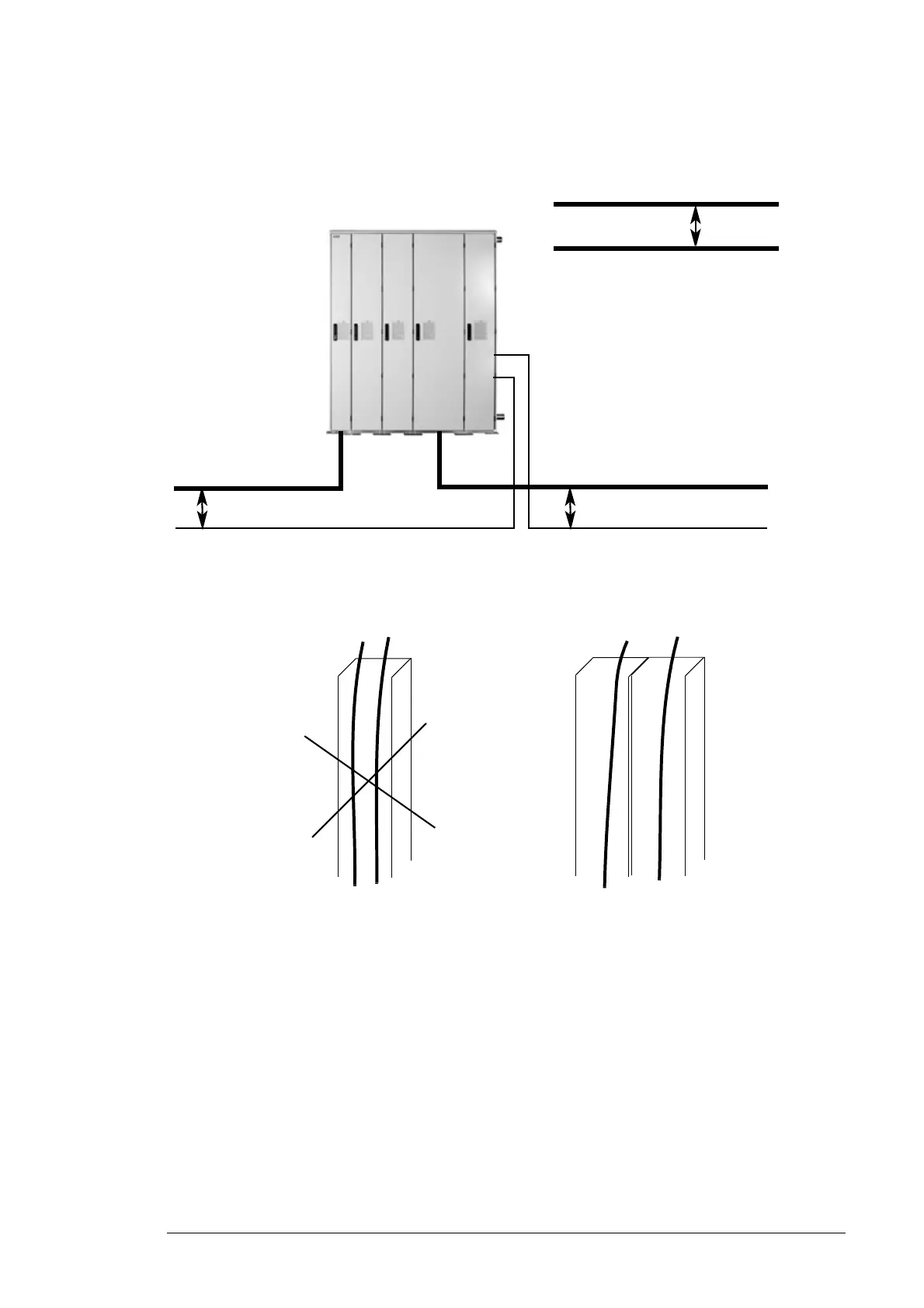
Planning the electrical installation 63
A
diagram of the cable routing is shown below
.
Control cable ducts
min 500 mm (20 in.)
Rotor cable
Grid cable
Control cables
min 300 mm (12 i
n.)
Rotor cable
Grid cable
Converter
min 200 mm (8 in.)
230
V (1
15
V)
24
V
24
V
230
V (1
15
V)
Lead 24
V and 230
V (1
15
V)
control cables in separate du
cts
inside the cabinet.
Not allowed unless the 24
V
cable is insulated for 230
V
(1
15
V) or insulated with an
insulation sleeving for 230
V
(1
15
V).
62
64
Table of Contents
Default Chapter
5
Table of Contents
5
1 Safety Instructions
11
What this Chapter Contains
11
Use of Warnings
11
Safety in Installation and Maintenance
12
Electrical Safety
12
Grounding
13
General Safety
13
Printed Circuit Boards
13
Fiber Optic Cables
13
Work with an Installation Stand and Lifting
14
Work on the Liquid Cooling System
14
Safe Start-Up and Operation
15
General Safety
15
2 Introduction to the Manual
17
What this Chapter Contains
17
Applicability
17
Target Audience
17
Purpose of the Manual
17
Contents of the Manual
18
Related Documents
18
Categorization by Frame Size and Option Code
18
Quick Installation, Commissioning and Operation Flowchart
19
Terms and Abbreviations
20
3 Operation Principle and Hardware Description
23
What this Chapter Contains
23
Operation Principle
23
Wind Turbine System with Low Voltage Stator (690 V)
24
Wind Turbine System with Medium Voltage Stator (> 1000 V)
24
Grid-Side and Rotor-Side Converters
25
Product Overview
26
Layout
26
Converter with 200 MM Wide Incoming Cubicle
27
Converter with 400 MM Wide Incoming Cubicle (Option +C111)
28
Power Modules
29
Crowbar
30
Smoke Detector
31
Power Cable Lead-Throughs
32
Blank Plate
32
Sealing Modules
32
Cable Glands
32
Control Interfaces
33
Circuit Boards
34
PC Tool Interfaces
35
Control Unit of the Grid-Side Converter
35
Control Unit of the Rotor-Side Converter
36
Control Unit NDCU-33Cx/Rdcu-12C
36
Voltage and Current Measurement Unit NUIM-61C/NUIM-10C
37
Auxiliary Measuring Unit NAMU-01C
38
Fiber Optic Links
38
Type Designation Labels
38
Type Designation Key
39
Basic Code
39
Option Codes (+ Codes)
40
4 Mechanical Installation
43
What this Chapter Contains
43
Safety
43
Checking the Installation Site
43
Required Tools
44
Unpacking
44
Checking the Delivery
44
Moving the Unit
45
Moving the Unit by Crane, Fork-Lift or Pallet Truck
45
By Crane
45
By Fork-Lift or Pallet Truck
45
Final Placement of the Unit
45
Overview of the Installation Procedure
46
Fastening the Cabinet to the Roof
47
Joining the Liquid Cooling Unit to the Converter Cabinet
49
Connecting the Liquid Pipes
49
Miscellaneous
50
Cable Duct in the Floor below the Cabinet
50
Electric Welding
51
Lifting the Door (Option +C161)
51
5 Planning the Electrical Installation
53
What this Chapter Contains
53
Selecting the Grid-Side Disconnecting Device (Disconnecting Means)
53
Checking the Compatibility of the Generator and Converter
54
Protecting the Generator Insulation and Bearings
54
Selecting the Power Cables
54
General Rules
54
Typical Power Cable Sizes
55
Iec
55
Alternative Power Cable Types
56
Rotor Cable Shield
57
Additional US Requirements
57
Conduit
58
Armored Cable / Shielded Power Cable
58
Suitable Power Supply Networks
59
TN-C-S Power Supply Network
59
TN-S Power Supply Network
59
Selecting the Grid-Side Power Cabling Principle
60
Alternative 1: Symmetrical, Shielded Three-Phase Cable(S)
60
Alternative 2: Cable Bus System
60
Alternative 3: Single Core Cables with Concentric Protective Shields
61
Selecting the Rotor Cabling Principle
61
Selecting the Control Cables
62
General Rules
62
Relay Cable
62
Control Panel Cable
62
Routing the Cables
62
Control Cable Ducts
63
Protecting the Converter, Grid Cable, Rotor and Rotor Cable in Short-Circuit Situation and against Thermal Overload
64
Protecting the Grid Cable in Short-Circuit Situations
64
Protecting the Converter in Short-Circuit Situations
64
AC Fuses
64
DC Fuses
64
Protecting the Rotor and Rotor Cable in Short-Circuit Situations
64
Protecting the Converter, Grid Cable and Rotor Cable against Thermal Overload
64
Protecting the Converter against Ground Faults in the Converter, Grid Cable, Rotor or Rotor Cable
65
Implementing the Emergency Stop Function
65
Supplying Power for the Auxiliary Circuits
65
Uninterrupted Auxiliary Power Supply for the Converter (UPS)
65
Auxiliary Power Supply for Converter (Non-UPS)
65
Planning the Installation of Equipment Connected to the Rotor Cable
66
Safety Switches, Contactors, Connection Boxes, Etc
66
Bypass Connection
66
6 Electrical Installation
67
What this Chapter Contains
67
Checking the Insulation of the Assembly
67
Converter
67
Grid Cable
67
Rotor and Rotor Cable
68
DC Resistor and Resistor Cable
68
Option +D150
68
Option +D150+D151
68
Connecting the Grid Cables - Units with 200 MM Wide Incoming Cubicle
69
Connection Diagram
69
Connection Procedure - a Blank Plate at the Cable Lead-Through
70
Connection Procedure - Sealing Modules at the Cable Lead-Through
71
Connection Procedure - Cable Glands at the Cable Lead-Through
73
Connecting the Grid Cables - Units with 400 MM Wide Incoming Cubicle (Option +C111)
74
Connection Diagram
74
Connection Procedure
74
Connecting the Rotor Cables
75
Connection Diagram
75
Connection Procedure - a Blank Plate at the Cable Lead-Through
76
Connection Procedure - Sealing Modules at the Cable Lead-Through
76
Connection Procedure - Cable Glands at the Cable Lead-Through
77
Control Connections
80
Connection Procedure
85
Connecting a PC
85
7 Installation Checklist
87
Mechanical Installation
87
Electrical Installation
87
Cooling Circuit
88
8 Maintenance
89
What this Chapter Contains
89
Maintenance Intervals
89
Power Connections
90
Tightening
90
Cleaning and Greasing
90
Fans
90
Replacing the Cooling Fan of the Converter Module
90
Replacing the Fan in the 400 MM Wide Incoming Cubicle (Option +C111)
93
Replacing the Fan in Auxiliary Control Cubicle
94
Converter Module
95
Replacing the Converter Module
95
Installing the Installation Stand
98
Capacitors
99
Reforming the Capacitors
99
Replacing the Capacitors
99
PPCS Branching Unit (APBU-XX)
100
Replacing the Memory Backup Battery
100
Replacing the Pressure Transmitter
101
Replacing DC Fuses
102
Bussmann Fuses
103
Mersen Fuses
103
Replacing AC Fuses (Option +C111)
104
Replacing the Capacitor of the LCL Filter
105
Replacing the Temperature Measurement Sensor
106
Replacing the Smoke Detector
107
Replacing the Main Contactor
108
Replacing the Charging Circuit Resistors
110
Replacing the Crowbar
111
Replacing the Crowbar Resistor
112
9 The Internal Cooling Circuit
113
What this Chapter Contains
113
Hardware Description
113
General
113
Diagram of the Internal Cooling Circuit
114
Planning the Cooling System
114
Connection to a Customer Cooling Unit
114
General Requirements
114
Additional US and Canada Requirements
115
Coolant Temperature Control
115
Mechanical Installation
115
Coupling the Internal Cooling Circuit to a Customer Cooling Unit
115
Maintenance
116
Filling up and Bleeding the Internal Cooling Circuit
116
Converter Line-Ups with a Customer Cooling Unit
116
Draining the Internal Cooling Circuit
117
Adding Inhibitor
117
Specifications
117
Temperature Limits
117
Pressure Limits
118
Water Quality
119
Freeze Protection and Corrosion Inhibition
119
Glycol Concentration
119
Approved Coolants
120
Materials
120
10 Technical Data
121
What this Chapter Contains
121
Ratings
121
Grid-Side Converter Ratings
121
Rotor-Side Converter Ratings
122
Definitions
122
Derating
122
Temperature Derating
122
Altitude Derating
122
Type Equivalence Table
123
Fuses
123
Main Circuit AC Fuses
123
Main Circuit DC Fuses
123
Dimensions and Free Space Requirements
124
Losses, Cooling Data and Noise
124
Internal Cooling Circuit Data
125
LCL Filter Data
125
Terminal and Lead-Through Data for the Power Cables
125
Terminal and Lead-Through Data for the Control Cables
126
Electric Power Network Specification
127
Generator Connection Data
127
DC Resistor Connection Data
128
DC Connection Data
128
Efficiency
128
Degree of Protection
128
Ambient Conditions
128
Materials
129
Auxiliary Circuit Current Consumption
129
Cooling Fans
129
UPS Supply
129
Non-UPS Supply
129
Applicable Standards
130
Grid Codes
130
CE Marking
130
Compliance with the European Low Voltage Directive
130
Compliance with the European EMC Directive
130
Compliance with the European Machinery Directive
130
Declaration of Incorporation
131
Validating the Operation of a Safety Function
132
Authorized Person
132
Acceptance Test Reports
132
Compliance with the en 61800-3
132
Definitions
132
Category C3
132
Category C4
133
UL Marking
133
UL Checklist
133
CSA Marking
134
C-Tick Marking
134
Disclaimer
134
11 Dimension Drawings
135
What this Chapter Contains
135
ACS800-67LC-1075/0575-7 and -1375/0575-7
136
With 400 MM Wide Incoming Cubicle (Option +C111)
137
Acs800-67Lc-1375/1125-7
138
With 400 MM Wide Incoming Cubicle (Option +C111)
139
ACS800-67LC-1595/0865-7 and -2035/1125-7
140
With 400 MM Wide Incoming Cubicle (Option +C111)
141
Sealing Modules for Grid Cables
142
Option +1H370
142
Options +1H370 and +C111
142
Options +2H370 and +C111
143
Option +1H371
143
Options +1H371 and +C111
144
Options +2H371 and +C111
144
Option +H378
145
Options +H378 and +C111
145
Sealing Modules for Rotor Cables
146
Option +1H372
146
Option +2H372
147
Option +3H372
148
Option +1H373
149
Option +2H373
150
Option +3H373
151
Option +H375
152
Further Information
153
Product and Service Inquiries
153
Product Training
153
Providing Feedback on ABB Drives Manuals
153
4
Based on 1 rating
Ask a question
Give review
Questions and Answers:
Need help?
Do you have a question about the ABB ACS800-67LC and is the answer not in the manual?
Ask a question
ABB ACS800-67LC Specifications
General
Brand
ABB
Model
ACS800-67LC
Category
Media Converter
Language
English
Related product manuals
ABB ACS800-67
120 pages
ABB ACS880-1607LC
148 pages
ABB ACS880-87LC-4000A/4021A-7
144 pages
ABB ACS140
107 pages
ABB ACS 301-1P6-3
101 pages
ABB ACS 300 Series
101 pages
ABB ACS 600 MultiDrive
102 pages
ABB ACA 6 Series
102 pages
ABB TEIP11
24 pages
ABB DCS 600
48 pages
ABB DCS 500B
228 pages
ABB CC Series
12 pages

 Loading...


