Operation principle and hardware description 27
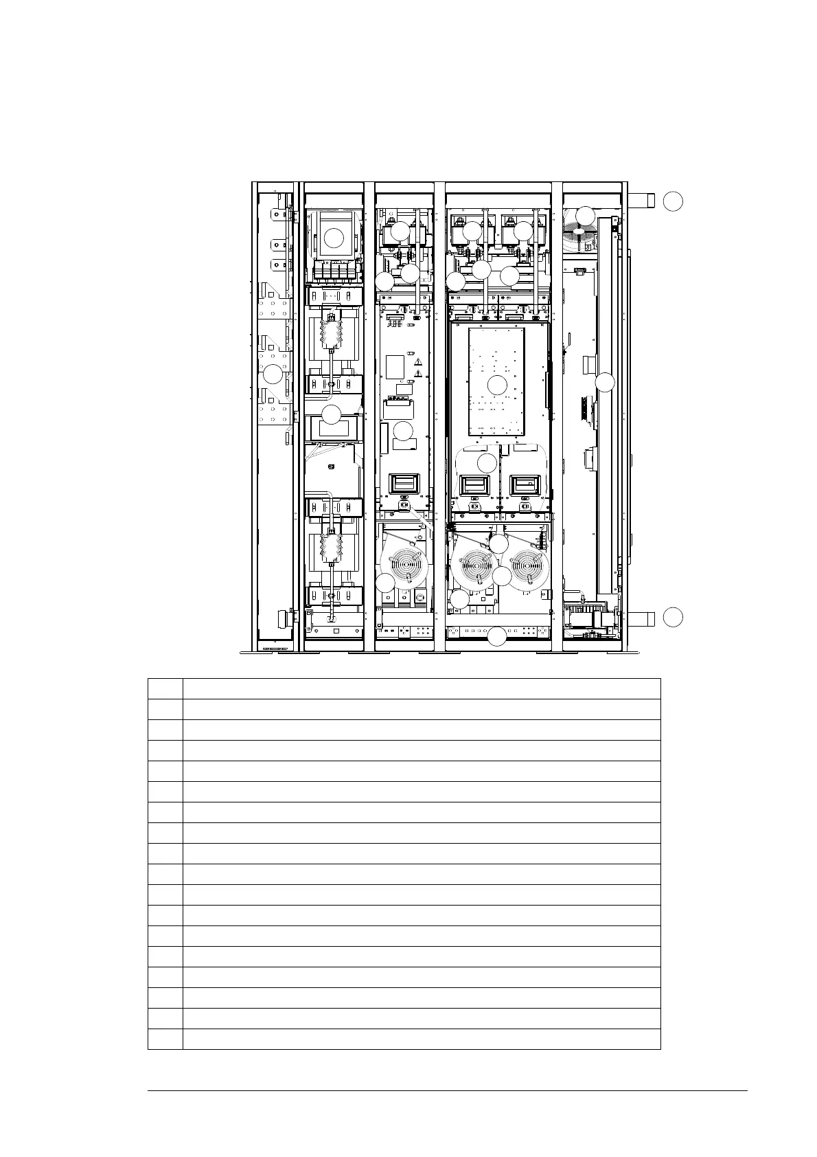
Converter with 200 mm wide incoming cubicle
No. Description
1 Grid-side power cable terminals (busbars)
2 Grid-side converter contactor K1 behind the charging circuit
3 LCL filter
4 IGBT supply module
5 Inverter modules (behind the swing-out frame of the crowbar)
6 Module cooling fans
7 Auxiliary control unit cooling fan
8 Rotor-side power cable terminals (behind removable fans)
9 PE terminal (cabinet grounding busbar behind the coolant pipe)
10 Sliding frame with control electronics
11 DC link fuses
12 Coolant inlet pipe
13 Coolant outlet pipe
14 Common mode filters
15 Crowbar (in the swing-out frame)
16 Smoke detectors
17 Common mode filter of crowbar
1
2
3
4
5
6
8
9
10
7
11 11
13
12
Doors open, shrouds removed
6
17
16
15
14
16
14
14
11

 Loading...


