Operation principle and hardware description 25
With the rotor-side converter (INU) it is possible to control the generator torque or speed
and the power factor at the rotor/stator terminals, while the main task of the grid-side
converter (ISU) is to keep the DC link voltage constant. While the rotor is accelerated by
the wind and the speed is controlled by the pitch of the blades the converter can be started
and controlled in DTC mode. After the grid-side converter has charged the intermediate
DC link properly and the rotor-side converter has magnetized the generator properly
(correct voltage magnitude and phase sequence), the circuit breaker of the stator (MCB3)
can be closed. When the converter is synchronized to the power supply network it is ready
to feed power to the grid. In order to stop the converter the breakers have to be opened
and the rotor is braked to standstill by pitch control and mechanical brakes.
Grid-side and rotor-side converters
The grid-side converter is an IGBT based module equipped with a line filter (LCL),
contactor, DC fuses and optional devices. It has RDCU-12 control unit with grid-side
control program. The converter is controlled by the rotor-side converter control unit via a
fiber optic link. RDCU-12C control unit contains RDCO DDCS communication option
module containing fiber optic terminals.
The grid-side converter rectifies three phase AC current to direct current for the
intermediate DC link of the converter. The intermediate DC link supplies the rotor-side
converter. The line filter suppresses the AC voltage and current harmonics.
As default, the grid-side converter controls the DC link voltage to the peak value of the
phase-to-phase voltage. The control of the IGBT power semiconductors is based on the
Direct Torque Control (DTC) method typically used in motor control of the converter. Two
line currents and DC link voltage are measured and used for the control.
The rotor-side converter consists of IGBT based inverter modules and employs the
NDCU-33C control unit. The converter is equipped with the doubly-fed induction generator
control program which also controls the grid-side converter module(s) via a fiber optic link.
The rotor-side converter modules control the torque of the generator and the power factor
at the stator/rotor terminals.
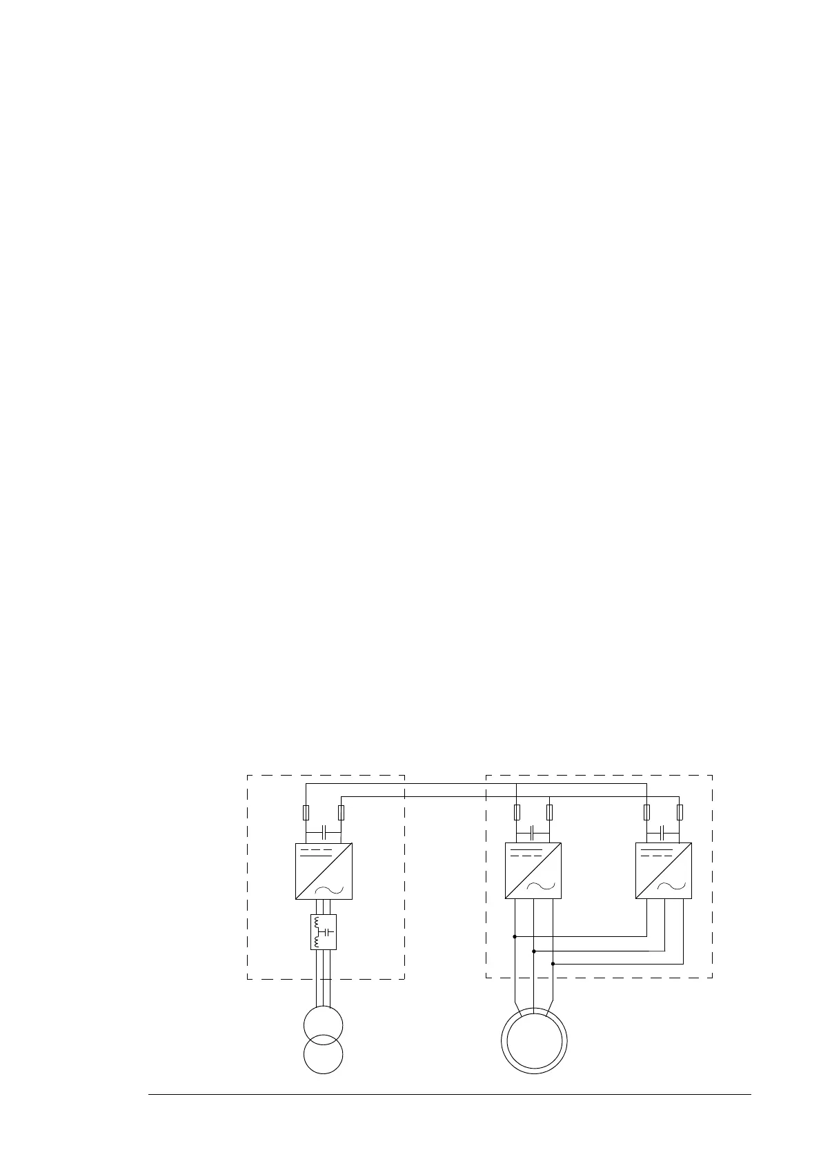
The diagram below shows an example of a common DC link converter system. In this
example the converter consists of one grid-side converter module and two parallel
connected rotor-side converter modules.
DC linkGrid-side converter Rotor-side converter
to doubly-fed induction
generator rotor
to power supply network
G

 Loading...


