Planning the electrical installation 55
Compared to the four conductor system, the use of symmetrical shielded cable reduces
electromagnetic emission of the whole converter system as well as generator bearing
currents and wear.
Note: The cabinet configuration of the converter may require multiple supply and/or
generator cabling. Refer to the connection diagrams in chapter Electrical installation.
The generator cable and its PE pigtail (twisted screen) should be kept as short as possible
in order to reduce electromagnetic emission as well as capacitive current.
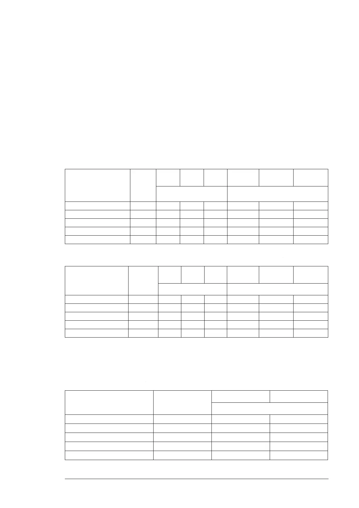
Typical power cable sizes
IEC
The maximum number of cables to be connected are shown below.
Rotor-side converter cables
Grid-side converter cables (or cables to the power cabinet (option +C109))
UL
The maximum number of cables to be connected are shown below. The cable ratings are
based on UL508A and National Electric Code 2008 (US).
Rotor-side converter cables
Type name
Rotor-
side
converter
current
rating [A]
240mm
2
185mm
2
120mm
2
3×240mm
2
+ 120mm
2
3×185mm
2
+
95mm
2
3×120mm
2
+
70mm
2
nr of cables / phase nr of cables
ACS800-67LC-1075/0575-7 898 2 3 4 3 3 4
ACS800-67LC-1375/0575-7 1143 3 4 5 3 4 5
ACS800-67LC-1375/1125-7 1143 3 4 5 3 4 5
ACS800-67LC-1595/0865-7 1334 4 4 6 4 5 6
ACS800-67LC-2035/1125-7 1697 5 5 7 5 6 8
Type name
Grid-side
converter
current
rating [A]
240mm
2
185mm
2
120mm
2
3×240mm
2
+
120mm
2
3×185mm
2
+
95mm
2
3×120mm
2
+
70mm
2
nr of cables / phase nr of cables
ACS800-67LC-1075/0575-7 480 1 2 2 2 2 2
ACS800-67LC-1375/0575-7 480 1 2 2 2 2 2
ACS800-67LC-1375/1125-7 941 3 3 4 3 3 4
ACS800-67LC-1595/0865-7 720 2 2 3 2 3 3
ACS800-67LC-2035/1125-7 941 3 3 4 3 3 4
Type name
Rotor-side converter
current rating [A]
500 kcmil (253 mm
2
) 350 kcmil (177 mm
2
)
nr of cables / phase
ACS800-67LC-1075/0575-7 898 4 5
ACS800-67LC-1375/0575-7 1143 6 8
ACS800-67LC-1375/1125-7 1143 6 8
ACS800-67LC-1595/0865-7 1334 6 9
ACS800-67LC-2035/1125-7 1697 9 11

 Loading...


