Operation principle and hardware description 33
Control interfaces
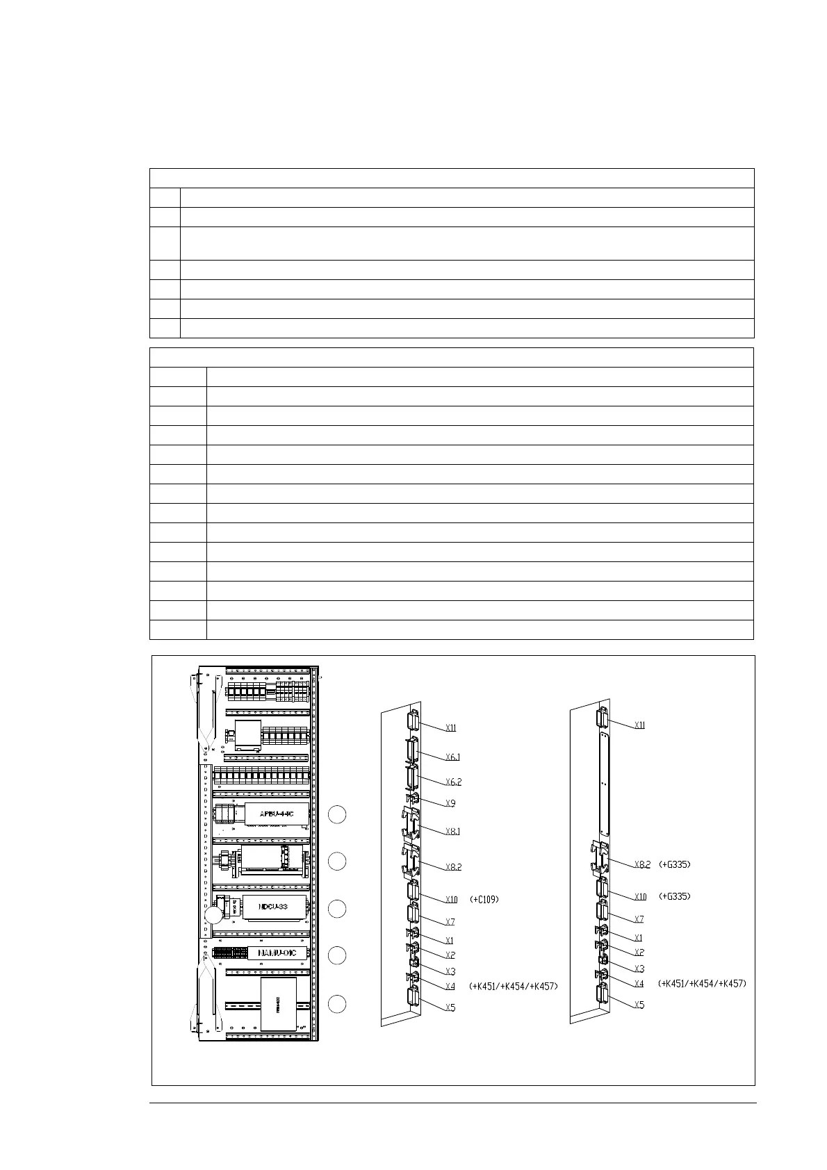
Control interfaces of the converter are described below.
Sliding frame in the auxiliary control cubicle
No. Description
1 APBU branching unit
2 RDCU unit. (If parallel connected grid-side converter modules are used, another APBU unit is located behind RMIO
board.)
3 NDCU unit
4 NTAC Pulse Encoder Interface module, optional fieldbus modules if ordered
5 NAMU measuring unit
6 NUIM voltage and current measuring unit
Control interfaces at the side of the cabinet
Terminal Description
X1 230 V AC supply (non-UPS)
X2 230 V AC supply (UPS)
X3 Ethernet
X4 Fieldbus
X5 Safety circuit and control signals
X6.1 External grid MCB control
X6.2 External stator MCB control
X7 Pulse encoder
X8.1 Grid voltage measurement
X8.2 Stator voltage measurement. Marked with X80 when option +G335 is selected.
X9 Stator current measurement
X10 ICU auxiliaries. Marked with X90 when option +G335 is selected.
X11 Grid MCB trip and on/off status (and Interbus option +K453)
PC tool interface (sliding frame)
Control interfaces at the side of the cabinet. Note: Connectors vary
depending on the selected options.
1
2
3
4
5
6
ICU200 or ICU400
(option +C111)
ICU800 (option +C108)

 Loading...


