Home
Allen-Bradley
Power distribution unit
825-P
Allen-Bradley 825-P User Manual
4
of 1
of 1 rating
266 pages
Give review
Manual
Specs
To Next Page
To Next Page
To Previous Page
To Previous Page
Loading...
Rockwell Automation Publication 825-UM0
04D-EN-P - November 2012
103
Con
figuring Pr
ot
ection & Logic F
unctions
Chapter
6
Ov
e
rloa
d C
urv
es
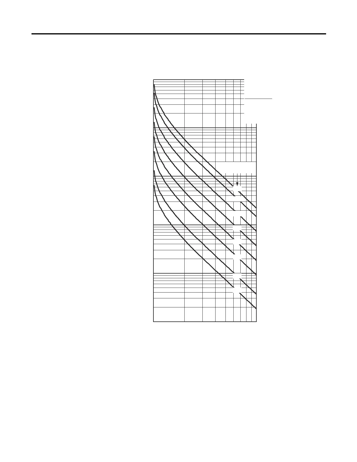
Figure 34 - Th
ermal Overload Cur
ves
100000
10000
1000
100
10
1
12
Multiples of Full Load Amps
Trip Time in Seconds
34
5
6
7
8
9
1
0
600
400
200
100
50
25
10
5
Locked Rotor Time
(in seconds)
Trip times are for cold
(ambient) motor, without preload.
Service Factor, SF = 1.01
Acceleration Factor, TD = 1.00
Run State Time Constant, RTC = Auto
Motor LRC = 6.0 • I
e
Relay Settings
102
104
Table of Contents
Default Chapter
2
Important User Information
2
EMC Directives
3
European Communities (EC) Directive Compliance
3
Low Voltage Directive
3
Table of Contents
5
Manual Overview
11
Preface
11
Conventions
12
Chapter 1
13
Features
13
Introduction
13
Overview
13
Options and Accessories
14
Applications
15
Chapter 2 Relay Placement
17
Physical Location
17
Relay Mounting
17
Installation
17
Rear-Panel Connections
18
Rear-Panel Diagram
18
Top-Panel Diagram
19
Power Connections
19
I/O Diagram
20
Ac/Control Connection Diagrams
21
Fail-Safe/Non-Fail-Safe Tripping
21
Converter Module Connection
23
Core Balance Current Transformer Connections
24
Voltage Connections
25
Full-Voltage Non-Reversing Starter
26
Full-Voltage Reversing Starter
28
Star-Delta Starting
28
Two-Speed Motor
30
Field Serviceability
31
Fuse Replacement
32
Real-Time Clock Battery Replacement
32
Chapter 3
33
Front Panel Layout
33
Front Panel Operation
33
Normal Front Panel Display
33
Front Panel Automatic Messages
34
Front Panel Menus and Operations
35
Front Panel Security
37
Front Panel Main Menu
40
View or Change Settings Using the Front Panel
41
Setting Entry Error Messages
43
Connecting a Converter Module (MCM)
45
Adding an Optional I/O Card
47
Chapter 4
47
Adding the Optional
48
Voltage Card
48
Adding the Optional Communication Card
49
Removing an Option Card
50
Chapter 5
51
Communications Settings
51
Software Overview
51
Connection/Access Level
52
Data Management
52
Button Summary
53
ANA (Test Analog Output)
54
MOT (Motor Operating Statistics)
54
SER (Serialized Events Recording)
55
STA (Relay Status)
55
SUM (Events Summary Report)
56
MET (Instantaneous Metering)
57
RTD (Rtd/Thermal Metering)
57
TAR (Display Target Words)
58
Configuration Files
53
Save/Open
53
Data Visualization/Trending
59
Validate Settings
61
I/O Mapping
62
Resetting/Restoring
63
Troubleshooting
63
Overview
65
Application Data
66
Chapter 6
66
Main Settings
66
Identifier Settings
66
Functions Application Data
66
Phase Rotation, Nominal Frequency Settings
67
Date Format
67
Settings
68
Voltage Transformer (VT) Configuration Settings
69
Basic Motor Protection
69
Overload (Thermal Model)
70
Short Circuit
74
Ground Fault
75
Jam
77
Undercurrent (Load Loss)
77
Current Imbalance
78
Phase Loss
78
Rockwell Automation Publication 825-UM004D-EN-P - November
78
Protection Disable
79
Start Monitoring
79
Star-Delta (Wye-Delta) Starting
80
Phase Reversal Protection
81
Start Inhibit
81
During Start)
82
Speed Switch
82
Thermistor (PTC) Monitoring
82
RTD-Based Protection
83
Voltage-Based Protection
86
Undervoltage
86
Overvoltage
87
VAR Function
87
Underpower
88
Power Factor
88
Frequency
89
Load Control Function
89
I/O Configuration
90
Analog Output
90
Trip Inhibit (Block)
91
Output Relay Behavior
92
Timer Function
93
Front Panel Settings
93
Display Enable
94
I/O Assignments
95
Logic Explanation
100
Stop/Trip Logic
100
Initiate Trip
100
Unlatch Trip
100
Start & Emergency Restart Logic
101
Overload Curves
103
Chapter 7
105
Metering
105
Instantaneous Metering
106
Thermal Metering
106
Metering & Monitoring
105
Overview
105
Power Measurement Conventions
107
Motor Operating Statistics
108
Chapter 8
109
Event Summary Reports
109
Overview
109
Serialized Events Recording (SER) Report
110
SER Triggering
110
Example Reports
111
Analyzing Events
109
Chapter 9
113
Introduction
113
Communication Card Features
115
Features
115
Required Equipment
116
Equipment Shipping with the Card
116
User-Supplied Equipment
116
Wiring
116
Node Commissioning
117
Setting the Hardware Switches
118
Using Rsnetworx for Devicenet
119
Explicit Messaging
121
Setting up the MSG Instruction
122
Devicelogix
124
Devicelogix Programming Example
125
Parameter Groups
129
Chapter 10 Installation
131
Mounting
131
Wiring
132
Overview
131
Commissioning
134
Modbus Queries
135
Modbus Responses
135
Supported Modbus Function Codes
135
Cyclical Redundancy Check
136
Modbus Exception Responses
136
Read Holding Register Command
136
Preset Single Register Command
137
Preset Multiple Registers Command
138
Read Parameter Information Command
139
Read Parameter Text Command
141
Read Enumeration Text Command
142
7Dh Encapsulated Packet with Control Command
143
7Eh NOP Command
144
Modbus Password Control and Parameter Modification
144
Modbus Load Profile Register Operation
145
Modbus Serialized Events Recording Register Operation
145
Chapter 11 Testing
147
Commissioning Tests
147
Rockwell Automation Publication 825-UM004D-EN-P - November
148
Selected Functional Tests
151
Periodic Tests (Routine Maintenance)
155
Overview
147
Troubleshooting
157
Field Serviceability
158
Power Supply Fuse Replacement
158
Real-Time Clock (RTC) Battery Replacement
159
Troubleshooting Device Backplane Communication
160
Troubleshooting Devicenet
160
ASCII Serial Communications
161
ASCII Serial Port Operation
161
Introduction
161
Required Equipment
161
Connect Your PC to the Relay
162
Configure Your Terminal Emulation Software
163
Chapter 12
161
Overview
161
Serial Port Settings
163
Using Terminal Commands
164
Serial Port Access Levels
165
Command Summary
166
Description of Commands
167
ACC and 2AC (Level 1 or 2)
167
ANALOG (Level 2)
167
DATE (Level 1 or 2)
167
METER (Level 1 or 2)
168
MOTOR (Level 1 or 2)
170
PASSWORD (Level 1 or 2)
170
QUIT (Level 1 or 2)
171
SER (Level 1 or 2)
171
SET (Level 2)
172
Show
173
STATUS (Level 1 or 2)
174
STOP (Level 2)
177
STR (Level 2)
177
SUMMARY (Level 1 or 2)
177
TARGET (Level 1 or 2)
178
TIME (Level 1 or 2)
179
View or Change Settings with Front Panel Serial Port
179
Chapter 13 Overview
183
Required Equipment
183
Upgrade Instructions
183
Firmware Upgrade Instructions
183
Appendix A
187
Electrical Ratings
187
Main Circuits
187
Control Circuits
188
Specifications
187
Mechanical Ratings
189
RTD Scanner Module
189
Electromagnetic Compatibility
190
Metering Accuracy
190
Processing
190
Standards
190
825-CBCT Core Balance Current Transformer
191
Primary Current Transformers
191
Devicenet Communication Card
192
Appendix B
193
Overview
193
Appendix C
235
Definitions
235
Overview
235
ASCII Port Relay
239
Appendix D
242
Appendix E
242
Devicenet Objects
242
Electronic Data Sheets
242
Product Codes
242
Identity Object - CLASS CODE 0X0001
243
Identity Objects - CLASS CODE 0X0001
243
Devicenet Object - CLASS CODE 0X0003
244
Message Router - CLASS CODE 0X0002
244
Assembly Object - CLASS CODE 0X0004
245
Instance 100
246
Custom Parameter-Based Input (Produced) Assembly Instance
246
Standard Input (Produced) Assemblies
247
Standard Output (Consumed) Assemblies
250
Connection Object - CLASS CODE 0X0005
251
Discreet Input Point Object - CLASS CODE 0X0008
254
Discrete Input Point Object - CLASS CODE 0X0008
254
Discreet Output Point Object - CLASS CODE 0X0009
255
Discrete Output Point Object - CLASS CODE 0X0009
255
Discrete Output Point Object Special Requirements
256
State Transition Diagram
256
Parameter Object - CLASS CODE 0X000F
257
Parameter Object - CLASS CODE 0X0010
258
Parameter Group Object - CLASS CODE 0X0010
258
Discrete Output Group Object - CLASS CODE 0X001E
259
Acknowledge Handler Object - CLASS CODE 0X002B
261
Control Supervisor Object - CLASS CODE 0X0029
261
Devicenet Interface Object - CLASS CODE 0X00B4
262
Overload Object - CLASS CODE 0X002C
262
4
Based on 1 rating
Ask a question
Give review
Questions and Answers:
Need help?
Do you have a question about the Allen-Bradley 825-P and is the answer not in the manual?
Ask a question
Allen-Bradley 825-P Specifications
General
Brand
Allen-Bradley
Model
825-P
Category
Power distribution unit
Language
English

 Loading...