Rockwell Automation Publication 825-UM004D-EN-P - November 2012 75
Configuring Protection & Logic Functions Chapter 6
When the harmonic distortion index is below the fixed threshold, the short
circuit overcurrent elements operate on the output of the cosine filter.
The cosine filter provides excellent performance in removing DC offset and
harmonics. However, the bipolar peak detector has the best performance in
situations of severe MCM/CT saturation when the cosine filter magnitude
estimation is significantly degraded. Combining the two filters ensures
dependable short circuit overcurrent element operation.
Ground Fault
Basic Information
Table 14 - Ground-Fault Core Balance Settings
The relay offers two types of ground-fault detecting elements. The CB elements
operate using current measured through an external core balance (zero sequence)
CT. The residual (RES) elements operate using a residual ground-fault
measurement from the MCM module.
While the ground-fault trip and warning levels offer an overall range of
0.01…25 A, the actual input circuitry has a dynamic sensing range of 5…500 mA.
Determine the range (in terms of primary amps) that is valid for a given
application by multiplying the input sensing range of 5…500 mA by the turns
ratio of the core balance sensor.
For information about corresponding valid ground fault setting ranges for typical
sensors, see Table 15.
Setting Prompt Setting Range Factory Default
GF-CB TRIP LEVEL Off, 0.01…25.00 A Off
GF-CB TRIP DELAY 0.00…5.00 s 0.00
GF-CB WARN LEVEL Off, 0.01…25.00 A Off
GF-CB WARN DELAY 0.0…120.0 s 10.0
NOTE: GF-CB Trip Level settings are in Primary Amperes.
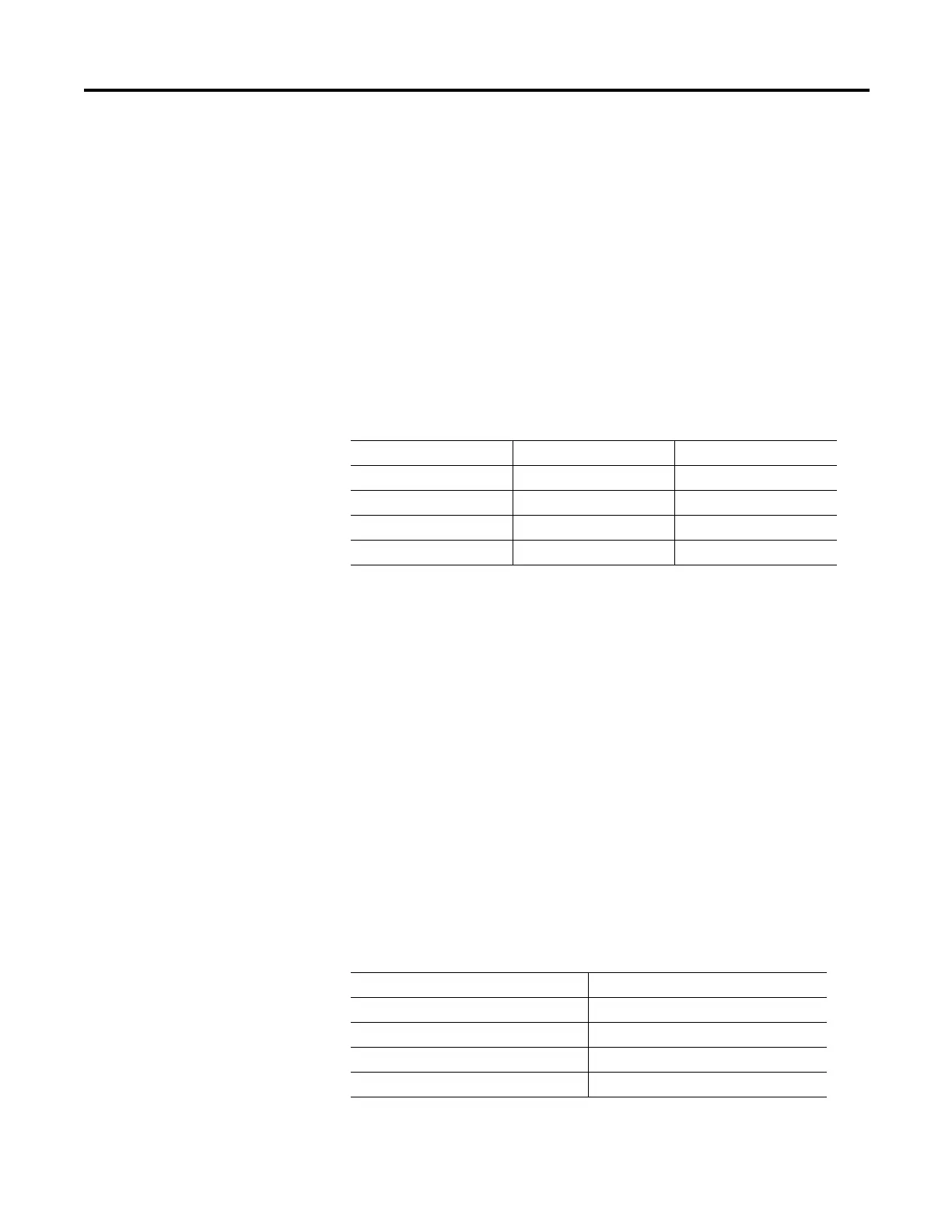
Table 15 - Ground-Fault Sensor-to-Settings Correlation
Ground Fault Sensor Ratio Valid Setting Range
1:1 0.01…0.50 A
50:5 0.10…5.00 A
100:1 1.00…25.00 A
2000:1 20.00…25.00

 Loading...