Rockwell Automation Publication 825-UM004D-EN-P - November 2012 87
Configuring Protection & Logic Functions Chapter 6
Overvoltage
When you connect the 825-P voltage inputs to phase-to-phase connected PTs,
as in Figure 12, the relay provides two levels of phase-to-phase overvoltage and
undervoltage elements.
When you connect the 825-P voltage inputs to phase-to-neutral connected PTs,
as in Figure 12, the relay provides two levels of phase-to-neutral overvoltage and
undervoltage elements.
Each of the elements has an associated time delay. You can use these elements
for tripping and warning. To disable an element, set the level setting to Off.
VAR Function
If the positive or negative reactive power exceeds the appropriate level for longer
than the time delay setting, the relay can issue a warning or trip signal. The
reactive power elements are disabled when the motor is stopped or starting.
Elements can be used to detect synchronous motor out-of-step or loss-of-field
conditions.
Refer to Power Measurement Conventions on page107 for the relay power
measurement convention.
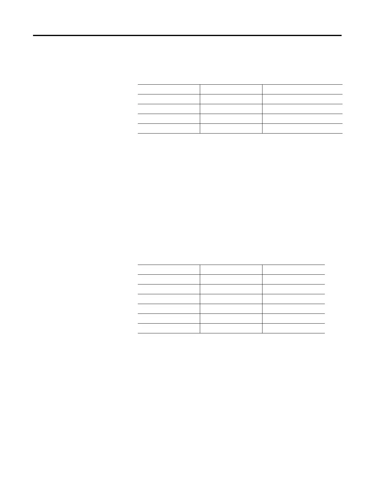
Table 29 - Overvoltage Settings
Setting Prompt Setting Range Setting Name := Factory Default
OV TRIP LEVEL Off, 1.00…1.20 xVnm Off
OV TRIP DELAY 0.0…120.0 s 0.0
OV WARN LEVEL Off, 1.00…1.20 xVnm Off
OV WARN DELAY 0.0…120.0 s 5.0
Table 30 - VAR Settings
Setting Prompt Setting Range Factory Default
NEG VAR TRIP LEV Off, 1…25000 KVAR Off
POS VAR TRIP LEV Off, 1…25000 KVAR Off
VAR TRIP DLY 0…240 s 1
NEG VAR WARN LEV Off, 1…25000 KVAR Off
POS VAR WARN LEV Off, 1…25000 KVAR Off
VAR WARN DLY 0…240 s 1
NOTE: VAR Trip and Warning Level settings are in Primary KVAR.

 Loading...