82 Rockwell Automation Publication 825-UM004D-EN-P - November 2012
Chapter 6 Configuring Protection & Logic Functions
Speed Switch (Stalling
During Start)
Speed Switch (stalling during start) protection provides mechanical sensing of a
locked rotor condition through input monitoring of a speed switch that is
mechanically coupled to the motor shaft. When the SS TRIP DELAY is set, the
relay trips if the speed switch is not closed within the set time after the motor
start begins. A separate delay, SS WARN DELAY, can also be set to provide a
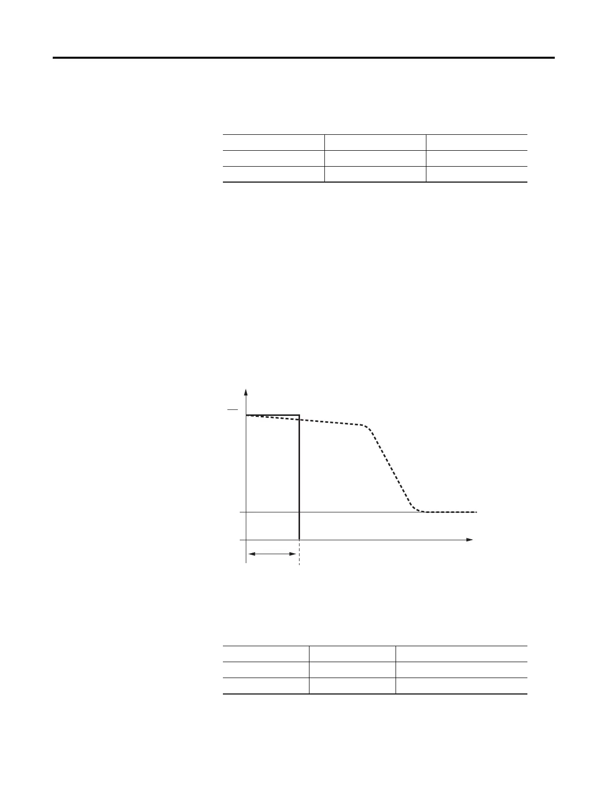
warning before the Speed Switch trip. Figure 31 shows typical currents during
motor start (normal and stall during start) and the Speed Switch Trip Delay time
setting.
Figure 31 - Stalling During Starting
Thermistor (PTC) Monitoring
Table 25 - Speed Switch Settings
Setting Prompt Setting Range Factory Default
SS TRIP DELAY Off, 1…240 s Off
SS WARN DELAY Off, 1…240 s Off
NOTE: In addition to setting the SS DELAY, you must connect the speed switch contact to an input
assigned to Speed Switch (see Table 44 and Figure 5, Figure 20, and Figure 21 for connection
diagrams).
I
1
2
I
t
v
t
I
e
I
e
1 =
2 =
t
v
=
Normal Start without Hindrance
by High Overload or Stalling
Stalling During Standing
SS TRIP DELAY Time
Table 26 - PTC Settings
Setting Prompt Setting Range Factory Default
PTC ENABLE Y, N N
PTC RESET MODE Man, Auto Man

 Loading...