Rockwell Automation Publication 825-UM004D-EN-P - November 2012 107
Metering & Monitoring Chapter 7
The thermal meter function also reports the state of connected RTDs if any have
failed. Table 48 shows failure messages.
Power Measurement
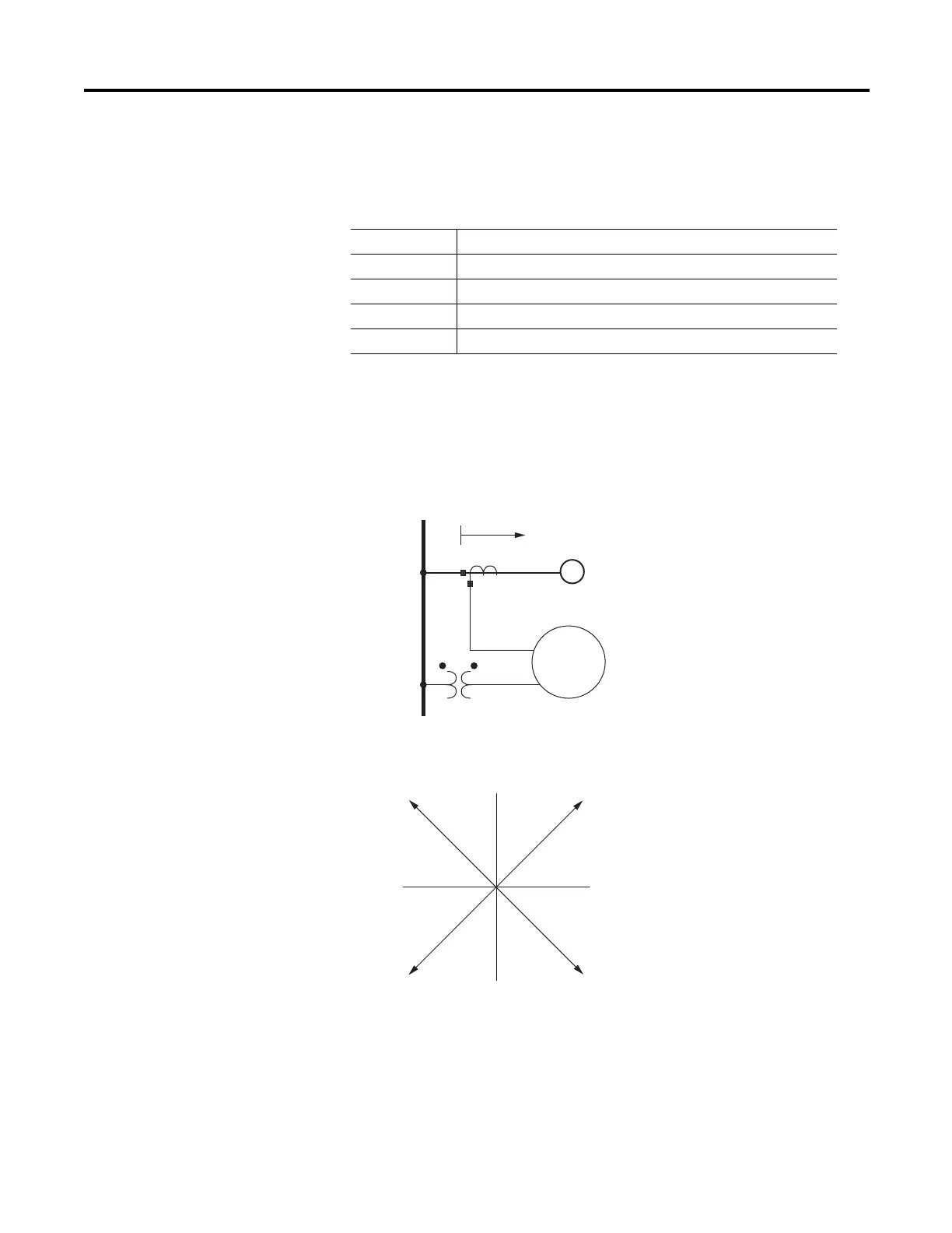
Conventions
The 825-P uses the IEEE convention for power measurement assuming motor
action. The implications of this convention are shown in Figure 35.
Figure 35 - Complex Power Measurement Conventions
In the 825-P, reported positive real power is always into the motor.
Table 48 - RTD Input Status Messages
Message Status
Open RTD leads open
Short RTD leads shorted
Comm Fail Fiber-optic communications to 825-PR12D Module have failed
Stat Fail 825-PR12D Module self-test status failure
Power Into Motor
Q+ (VAR)
I leads V
W = –
VAR = –
PF = LAG
I lags V
W = –
VAR = +
PF = LEAD
P+ (W)
I leads V
W = +
VAR = –
PF = LEAD
I lags V
W = +
VAR = +
PF = LAG
M
825-P
Relay
Source
Bus
Direction of
Positive Real Power
Motor

 Loading...