EasyManuals Logo
Home>Allen-Bradley>Power distribution unit>825-P

Allen-Bradley 825-P User Manual

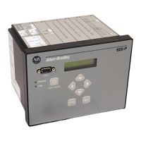
Allen-Bradley 825-P
266 pages
To Next Page IconTo Next Page
To Previous Page IconTo Previous Page
Page #24 background imageLoading...
Page #24 background image
24 Rockwell Automation Publication 825-UM004D-EN-P - November 2012
Chapter 2 Installation
Core Balance Current Transformer Connections
Figure 10 - Core Balance Current Transformer Connections
Figure 11 - 825-CBCT Dimensions [mm (in)]
825-CBCT
Ground Fault Sensor
(or customer-supplied
equivalent)
MCM/CWE
DEVICENET
L1
L2
L3
N
CBCT
S1
S2
S1
S2
BK
BU
SH
WH
RD
RTD
MODULE
RX
PTC
A1+
A2-
13
14
23
24
95
96
98
95
98
96
Y12
Y1-
Y14
T1
T2
0.31 in
8.0 mm
!
!!!
!
ZED
CB
A
Z E D
CB
A
157-0138
BUS
STATUS
NETWORK
STATUS
PGM
0 = 125K
1 = 250K
2= 500K
DATA
RATE
8 2
6 4
8 2
6 4
8 2
6 4
190-3011-01
NON-
FAIL-SAFE
FAIL-SAFE
-
+
80
(3.15)
175
(6.90)
Ø 110
(4.33)
Ø 9.0
(0.35)
35
(1.38)
150
(5.91)
200
(7.87)
175
(0.69)

Table of Contents

Questions and Answers:

Question and Answer IconNeed help?

Do you have a question about the Allen-Bradley 825-P and is the answer not in the manual?

Allen-Bradley 825-P Specifications

General IconGeneral
BrandAllen-Bradley
Model825-P
CategoryPower distribution unit
LanguageEnglish