30 Rockwell Automation Publication 825-UM004D-EN-P - November 2012
Chapter 2 Installation
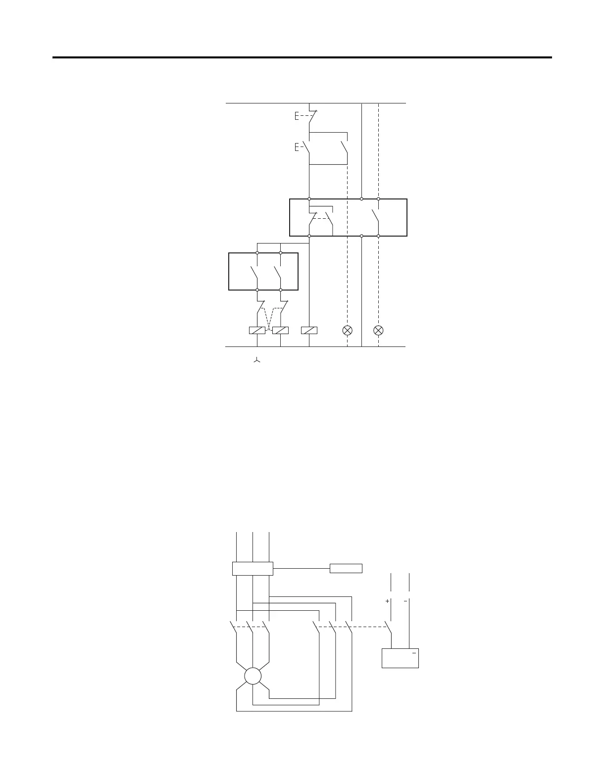
Figure 19 - Control Connections for Star-Delta Starting
Two-Speed Motor
The two-speed motor applications in the following figures require the following
input setting: IN1 = 0 0 0 0 0 0 0 1 0 0 (SPEED2)
Figure 20 - AC Connections for a Two-Speed Motor
NOTE: For AUX1 to work as an alarm/warning indicator, it must be mapped to the “Warning”
function bit.
K1
S1
S0
H1
TR
H3
AUX1
Contactor
On push button
Off push button
Indicator
"Contactor closed"
Main relay
Indicator "Alarm/Warning"
Alarm relay
TR
AUX1
S0
S1
95 A1 13
53
54
H1
A1
AUX5
825-P
825-P
AUX6
63
64
96
98
A2 14
K1
A1
A2
K3 K2
D
K1
H
A2
A1
A2
H3
NOTE: For AUX1 to work
as an alarm/warning
indicator, it must be mapped
to the "Warning" function bit.
13 5
L1 L2 L3
L
N
Y12 Y1
642
(II)(I)
825-P
825-P
825-MCM
24 V AC/V DC
M
3 ~

 Loading...