Rockwell Automation Publication 825-UM004D-EN-P - November 2012 157
Testing & Troubleshooting Chapter 11
Troubleshooting
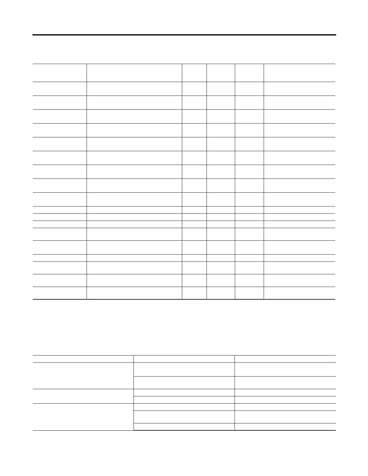
Refer to Table 90 for troubleshooting instructions in particular situations.
+5V Fail Measure +5V power supply <5.4V
>4.65V
Yes Latched +5V FAIL
+2.5V Warn Measure +2.5V power supply <2.60V
>2.42V
No Not Latched
+2.5V Fail Measure +2.5V power supply <2.68V
>2.32V
Yes Latched +2.5V FAIL
+3.75V Warn Measure +3.75 power supply <3.90V
>3.60V
No Not Latched
+3.75V Fail Measure +3.75 power supply <4.02V
>3.48V
Yes Latched +3.75V FAIL
-1.25V Warn Measure –1.25V power supply >–1.27V
<–1.20V
No Not Latched
-1.25V Fail Measure –1.25V power supply >–1.33V
<–1.16V
Yes Latched –1.25V FAIL
-5V Warn Measure –5V power supply >–5.2V
<–4.8V
No Not Latched
-5V Fail Measure –5V power supply >–5.4V
<–4.65V
Yes Latched –5V FAIL
CT Board A/D Fail Check received data Yes Latched CT BOARD ADC FAILURE
PT Board A/D Fail Check received data Yes Latched PT BOARD ADC FAILURE
Clock Battery Warn Check battery voltage level < 2.7V No Not Latched CLOCK BATTERY WARN
RTC Chip Unable to communicate with clock or fails time-
keeping test
No Not Latched RTC WARN
Temperature Warn Measure internal relay temperature >–40 C
<+85 C
No Not Latched TEMPERATURE WARN
Temperature Fail Measure internal relay temperature >+100 C Yes Latched TEMPERATURE FAIL
Mainboard FPGA Fail if mainboard Field Programmable Gate Array does
not accept program
Yes Latched FPGA FAIL
MCM/CWE Type Fail if the detected external converter module does not
match the part number
No MCM/CWE FAIL
Back-plane Comms
Diagnostics
Fail if GPSB is busy two processing intervals in a row Yes Latched GPSB FAIL
Table 89 - Relay Self-Tests (Sheet 2 of 2)
Self-Test Description Limits
Protection
Disabled on
Failure
Critical
Alarm Status
Front Panel Message
on Failure
Table 90 - Troubleshooting
Problem Possible Cause Solution
The relay enable front panel LED is not illuminated. Input power is not present or a fuse is blown. Verify that input power is present.
Check fuses continuity.
Self-test failure. View the self-test failure message on the front panel
display.
The relay front panel display does not show characters. The relay front panel has timed out. Press the Esc push button to activate the display.
The relay is de-energized. Verify input power and fuse continuity.
The relay does not accurately measure voltages or
currents.
Wiring error. Verify input wiring.
Incorrect Phase CT Ratio, Core B. CT Ratio, or Phase VT
Ratio setting.
Verify instrument transformer ratios, connections, and
associated settings.
Voltage neutral terminal (N) is not properly grounded. Verify wiring and connections.

 Loading...