3-78
Confidential
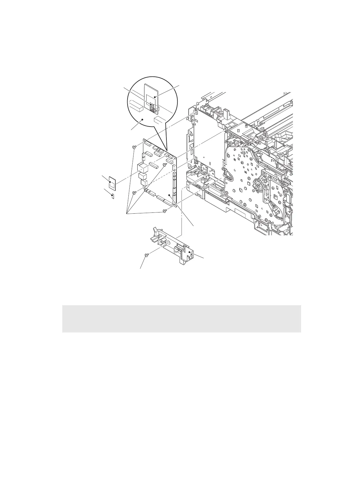
(2) Remove the tape, and disconnect the wireless LAN PCB. (Wireless LAN models only)
(3) Remove the screw cup M3x8 (black) screw, and remove the veil cover lower.
(4) Remove the four screw cup M3x8 (black) screws, and remove the main PCB ASSY.
Fig. 3-76
Assembling Note:
• When connecting the wireless LAN PCB to the main PCB ASSY, secure it using tape
as shown in the figure above.
Tape (Wireless LAN models only)
Wireless LAN PCB
(Wireless LAN models only)
Main PCB ASSY
Main PCB ASSY
Screw cup M3×8 (black)
Screw cup M3×8 (black)
Veil cover lower
Wireless LAN PCB
(Wireless LAN models only)
Tape
(Wireless LAN models only)
 Loading...