3-93
Confidential
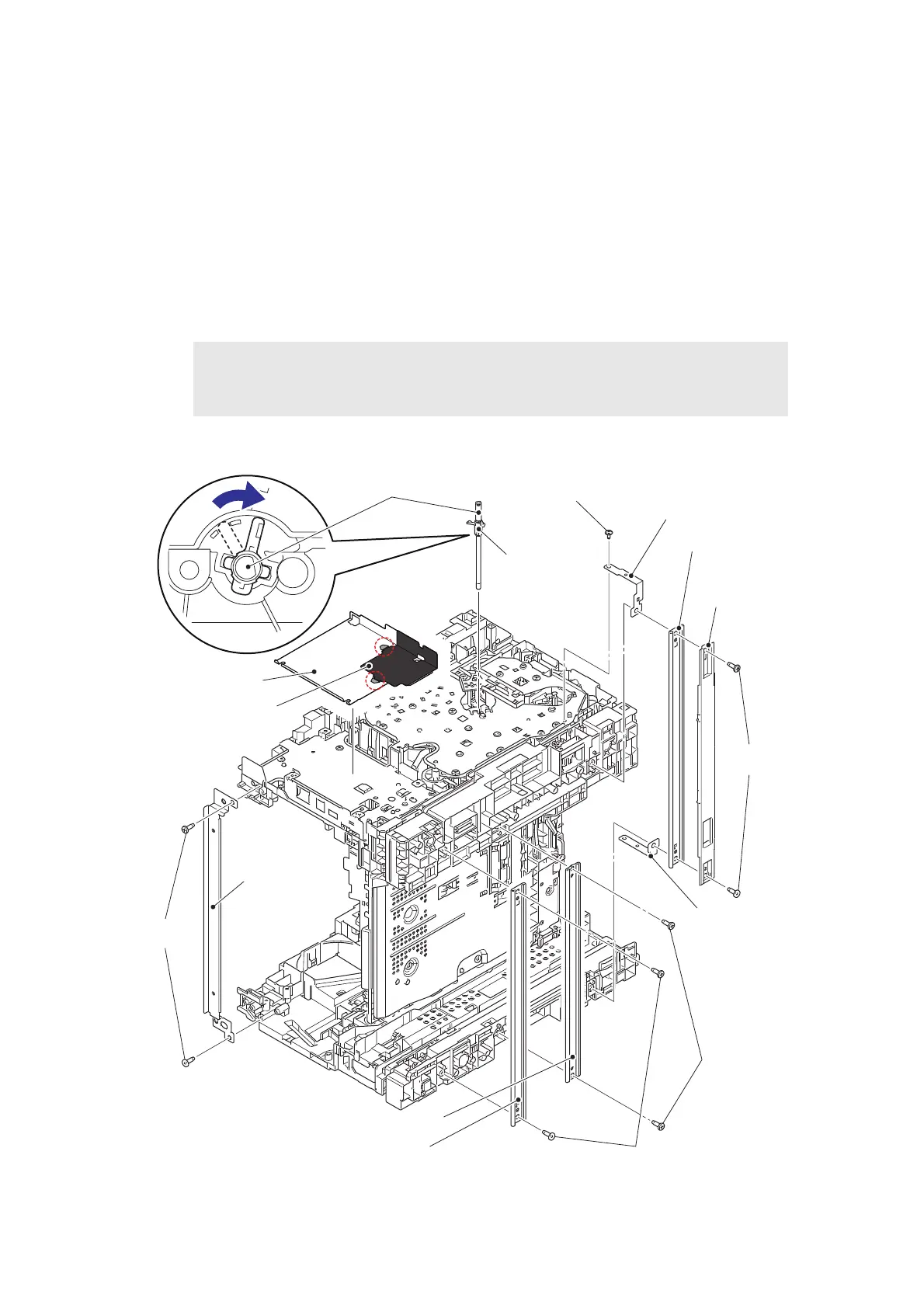
9.28 Main frame L ASSY
For models with 520-sheet T1
(1) Remove the two taptite bind B M4×12 screws, and remove the under bar rear.
(2) Remove the two taptite bind B M4x12 screws, and remove the under bar center.
(3) Remove the two taptite bind B M4×12 screws, and remove the under bar front, under bar
cover and under bar ground plate R.
(4) Remove the two taptite bind B M4x12 screws, and remove the top bar rear.
(5) Remove the taptite cup S M3x8 SR screw, and remove the under bar ground plate L.
(6) Remove the main PCB insulation sheet (transparent) and the main PCB insulation sheet
(black).
(7) Turn the registration roller bushing on the registration roller shaft to the position as
shown in the figure below, and pull out the registration roller shaft.
Fig. 3-93
Assembling Note:
• Make sure that the black main PCB insulation sheet is inserted properly into the hole
of the transparent main PCB insulation sheet as shown in the illustration below.
Under bar ground plate L
Under bar front
Under bar
ground plate R
Taptite bind
B M4x12
Registration roller shaft
Main PCB insulation
sheet (black)
Taptite bind B
M4x12
Taptite bind
B M4x12
Registration roller
bushing
Taptite cup S M3x8 SR
Main PCB insulation
sheet (transparent)
Under bar rear
Taptite bind B M4x12
Under bar cover
Top bar rear
Under bar center
 Loading...