3-80
Confidential
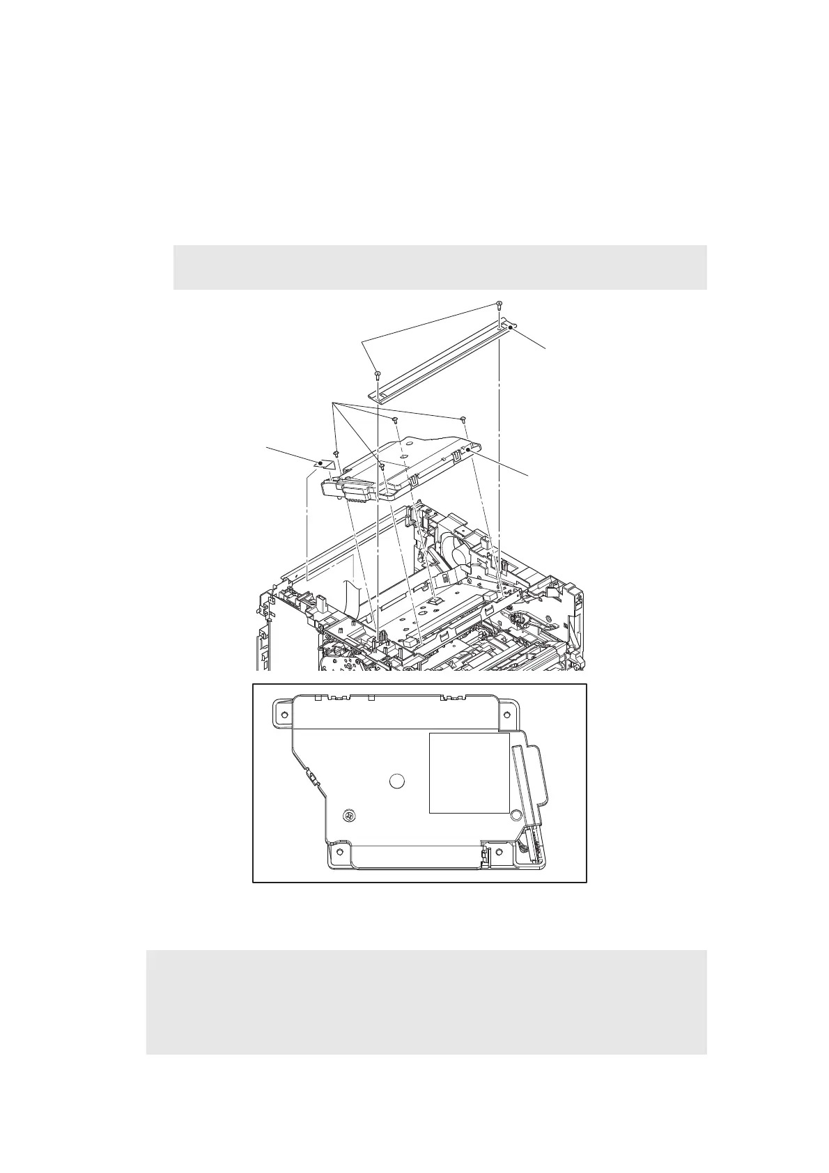
9.20 Laser unit
(1) Remove the two taptite bind B M4x12 screws, and remove the top bar. (Models with
520-sheet T1 only)
(2) Disconnect the laser unit flat cable from the laser unit, and release it from the securing
fixtures.
(3) Remove the four taptite cup S M3x8 SR screws, and remove the laser unit.
Fig. 3-78
Harness routing: Refer to “10. Left side of the machine”, “11. Rear side of the machine”.
Note:
• Be careful not to touch the lens of the laser unit.
Assembling Note:
• When attaching the laser unit, tighten the screws in the following order: upper right,
lower right, lower left and upper left.
• When connecting flat cables, do not insert them at an angle. After insertion, check that
the cable is not at an angle.
Laser unit flat cable
Laser unit
1
2
3
4
Top bar
(Models with 520-sheet T1 only)
Taptite bind B M4x12
Taptite cup S M3x8 SR
 Loading...