Do you have a question about the Cisco 15216 EDFA2 and is the answer not in the manual?
| Device Type | Optical Amplifier |
|---|---|
| Noise Figure | ≤ 5.5 dB |
| Product Type | EDFA |
| Operating Temperature | 0°C to 50°C |
| Storage Temperature | -40°C to 70°C |
| Number of Ports | 2 |
Describes bandwidth-on-demand wavelength services, guaranteeing amplification for each wavelength.
Explains restoring lost wavelengths via rerouting around a ring in case of fiber cuts.
Details the main features of the ONS 15216 EDFA2, including gain, noise, and management protocols.
Lists optical parameters like wavelength, input power, output power, and gain.
Details input power limits and the effects of exceeding them on the unit's lifespan.
Explains how to calculate per-channel power for smooth upgrades and avoid disruption.
Lists electrical requirements including input voltage, power consumption, and maximum current.
Provides physical specifications such as dimensions, weight, operating temperature, and humidity.
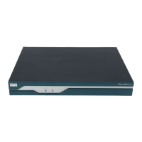
Describes the external components and features of the ONS 15216 EDFA2.
Details the front panel layout, including ports, LEDs, and monitoring features.
Outlines the chapter's content covering installation procedures for the ONS 15216 EDFA2.
Lists essential safety precautions to be taken before and during installation.
Covers considerations for rack placement and procedures for connecting power.
Details the SC/UPC optical ports, including safety requirements and connection procedures.
Describes communication methods: Alarm Out, LEDs, Serial, and LAN interfaces.
Explains how to establish communication using a serial connection via HyperTerminal.
Details the procedure for establishing remote dial-up modem communication.
Explains how to connect to the ONS 15216 EDFA2 via an Ethernet LAN for remote access.
Steps to log in via RS-232 port to set the IP address before LAN access.
Mandatory procedure to set the module's IP address through the RS-232 serial interface.
Optional procedure for provisioning the module using Telnet over the LAN port.
Command to set the amplifier gain correctly for transceiver reception in the network element.
Sets alarm thresholds to notify the network operator of valid alarms via RJ-45 ports.
Command to change the default user password to restrict access to the ONS 15216 EDFA2.
Saves the system configuration to a file for later use or to configure other units.
Restores the system configuration from a file, replacing existing configuration data.
Procedure to reset the root password to regain full administrative control.
Explains SNMP as a protocol for network device management and information retrieval.
Describes how SNMP communities enforce security through password-like strings.
Procedure to configure the ONS 15216 EDFA2 for Cisco Transport Manager (CTM) access.
Lists key tables within the MIB used for provisioning and reviewing data.
Explains how to configure traps for asynchronous notifications sent to a predetermined location.
Details SNMP commands used to access ONS 15216 EDFA2 information like IP address and time.
Command to display the ONS 15216 EDFA2's IP address and other networking information.
Covers retrieving case temperature values and alarm thresholds.
Procedures for backing up and restoring system configuration information.
Provides a summary of the ONS 15216 EDFA2's SNMP alarms and their descriptions.
Lists ASH commands and their corresponding user access levels (R, RW, RWA).
Details useful commands for configuring the ONS 15216 EDFA2.
Lists commands useful for administering the ONS 15216 EDFA2.
Useful commands for working with the ONS 15216 EDFA2 shell environment.
Commands for managing files on the ONS 15216 EDFA2 Flash memory.
Commands for working with the SNMP protocol for provisioning and configuration.
Commands for setting up and maintaining user accounts on the ONS 15216 EDFA2.
Commands to retrieve manufacturing-related information from the ONS 15216 EDFA2.
Commands for backing up and restoring system configuration.
Enables access to manufacturer-specific commands for advanced operations.
Explains how to use the FTP command line for file transfer between FTP server and ONS 15216 EDFA2.
Lists available FTP commands and their syntax for file management.
Steps to log in via RS-232 port to set IP address before LAN access.
Mandatory procedure to set the module's IP address via RS-232 interface using TL1.
Optional procedure for provisioning via Telnet, requiring a Telnet client.
Command to set amplifier gain correctly for transceiver reception using ED-DWDM.
Sets alarm thresholds for network operator notification via RJ-45 ports.
Command to change the default user password using ED-PID for access restriction.
Command to add new users with specified access levels and passwords using ENT-USER-SECU.
Restores system configuration from a file on the FFS using CPY-MEM.
Provides details of TL1 commands and maps parameters to SNMP attributes.
Explains common TL1 command parameters like sid, tid, ccm, aid, and ctag.
Summarizes the ONS 15216 EDFA2's autonomous alarms and events.
Summarizes security permissions (access levels) for TL1 commands and messages.
Details various TL1 commands and their syntax for system provisioning.
Configures the ONS 15216 EDFA2 optical control parameters.
Configures the ONS 15216 EDFA2 environmental (power bus) parameters.
Edits general parameters like SID, IP address, mask, and boot table content.
Edits user password using the ED-PID command.
Generates a report on all active alarms, excluding environmental alarms.
Generates a report on the condition (state) of all alarms, excluding environmental alarms.
Retrieves the ONS 15216 EDFA2 optical control configuration.
Retrieves the ONS 15216 EDFA2 environmental parameter configuration.
Retrieves general parameters like SID, IP address, mask, and boot table content.
Retrieves optical threshold and set point values for the ONS 15216 EDFA2.
Sets optical threshold values for the ONS 15216 EDFA2.
Sets general threshold values for the ONS 15216 EDFA2.
Restores all manufacturing default settings, requires INIT-SYS afterward.
Describes alarm indicators including LEDs and office alarms.
Explains the function of front panel LEDs (POWER, FAIL, LOS, Ethernet).
Details optical alarms: LOS, GAIN, and LPOUT, related to signal amplification.
Lists equipment alarms: CTMP, LCRNT1, LCRNT2, LTMP1, and LTMP2.
Describes environmental alarms related to power bus voltage.
Provides procedures for common troubleshooting scenarios.
Addresses the issue of no output power after gain settings modification.
Troubleshooting steps for failures during the unit's boot-up process.
Steps to troubleshoot issues when the RS-232 port does not respond.
Steps to troubleshoot issues when the LAN port does not respond.
Procedure to reset the lost root password to regain administrative control.
Lists commands to collect necessary status information for Cisco TAC interaction.
Details regulatory standards compliance for EMC, Safety, Environmental, and Telecom.
Provides translations of safety warnings required by various countries.
Explains the meaning of the warning symbol indicating potential danger and injury.
Warns about handling DC power supply wiring and connections.
Advises reading installation instructions before connecting to power source.
Instructs to disconnect power cords before servicing units with multiple power supplies.
Warns about connecting SELV circuits only to other SELV circuits.
Warns about invisible laser radiation hazards and required eye protection.
Instructs to disconnect input connector first, then output connector for fiber cables.
Advises not to look directly at optical connector output beams to avoid eye damage.
Warns that static electricity can damage electro-optical modules and advises grounding.
Instructs to power down module and disable laser before cleaning connectors.
Advises reconnecting output connectors first, then input connectors for fiber cables.
Warns that module removal causes traffic failure and requires authorization.
States DC power systems must comply with safety extra-low voltage (SELV) requirements.
Requires reinforced insulation (RI) between AC power and 48 VDC output.
Warns that abnormal power supply voltage must not exceed -60.0 VDC.
Instructs to use appropriate lugs for DC power supply wiring.