If the latch is not fully engaged, you might accidentally disconnect the QSFP+ or QSFP28 transceiver module.
Caution
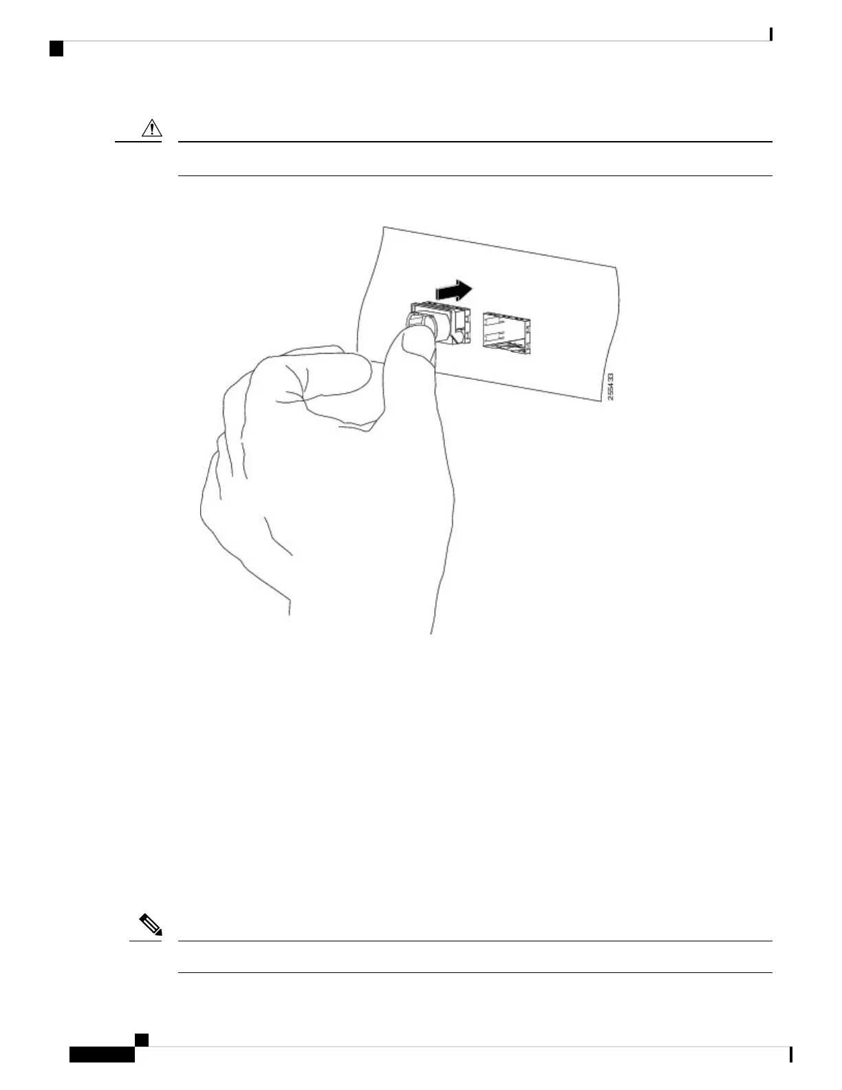
Figure 73: Seating the 40-Gigabit QSFP+ or 100-Gigabit QSFP28 Transceiver Module (Optical Transceiver Equipped with a Bail-Clasp
Latch Shown)
8. For optical QSFP+ or QSFP28 transceiver modules, reinstall the dust plug into the QSFP+ or QSFP28
transceivers optical bore until you are ready to attach the network interface cable. Do not remove the dust
plug until you are ready to attach the network interface cable.
Attaching the Optical Network Cable
Before removing the dust plugs and making any optical connections, follow these guidelines:
• Keep the protective dust plugs installed in the unplugged fiber-optic cable connectors and in the
transceiver optical bores until you are ready to make a connection.
•
• Inspect and clean the MPO connector end faces just before you make any connections. See Cleaning
Fiber-Optic Connectors, on page 133.
• Grasp the MPO connector only by the housing to plug or unplug a fiber-optic cable.
40-Gigabit QSFP+ or QSFP28 transceiver modules are keyed to prevent incorrect insertion.
Note
Cisco ASR 9000 Series Aggregation Services Router Ethernet Line Card Installation Guide
118
Installing and Removing Line Cards and Transceiver Modules
Attaching the Optical Network Cable
 Loading...


