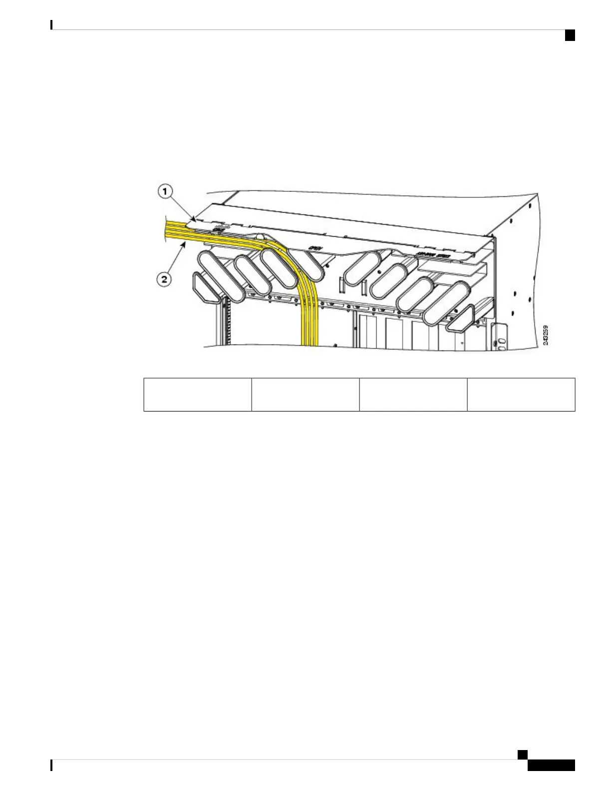
Cable Management Tray
A cable-management tray is mounted at the top of the Cisco ASR 9010 Router chassis for routing interface
cables to the RSP and line cards. The figure below shows a typical cable routing through the cable-management
tray. The tray has a hinged cover that can be raised for greater access to the cable management dividers.
Figure 78: Example Cable Routing through the Cisco ASR 9010 Router Cable Management Tray
Cable bundle routed
through the tray
2Hinged cover (shown in
the raised position)
1
Each line card has its own cable routing slot in the cable management tray. For example, the cables shown in
the figure above are cables being routed to line card 3 in slot 3 in a Cisco ASR 9010 Router.
Router Cable Management Brackets
The Cisco ASR 9006 Router provides for a cable management bracket on each side of the router chassis. The
following figure shows a typical cable routing for the Cisco ASR 9006 Router.
Each line card has its own cable routing slot in the Cisco ASR 9006 Router cable management brackets. For
example, the cables shown in the following figure show the cables being routed to line card 0 in slot 3 and
line card 2 in slot 5.
Cisco ASR 9000 Series Aggregation Services Router Ethernet Line Card Installation Guide
125
Installing and Removing Line Cards and Transceiver Modules
Cable Management Tray
 Loading...


