MPO-24 Connector Pin Specifications
The following figures show the pinouts and corresponding fiber numbers for the CPAK multifiber push-on
(MPO-24) male connector in 100G mode and 2X40G mode.
In the following figures, the male MPO connector alignment pins are on the CPAK side so the cable MPO
connectors will be female.
Note
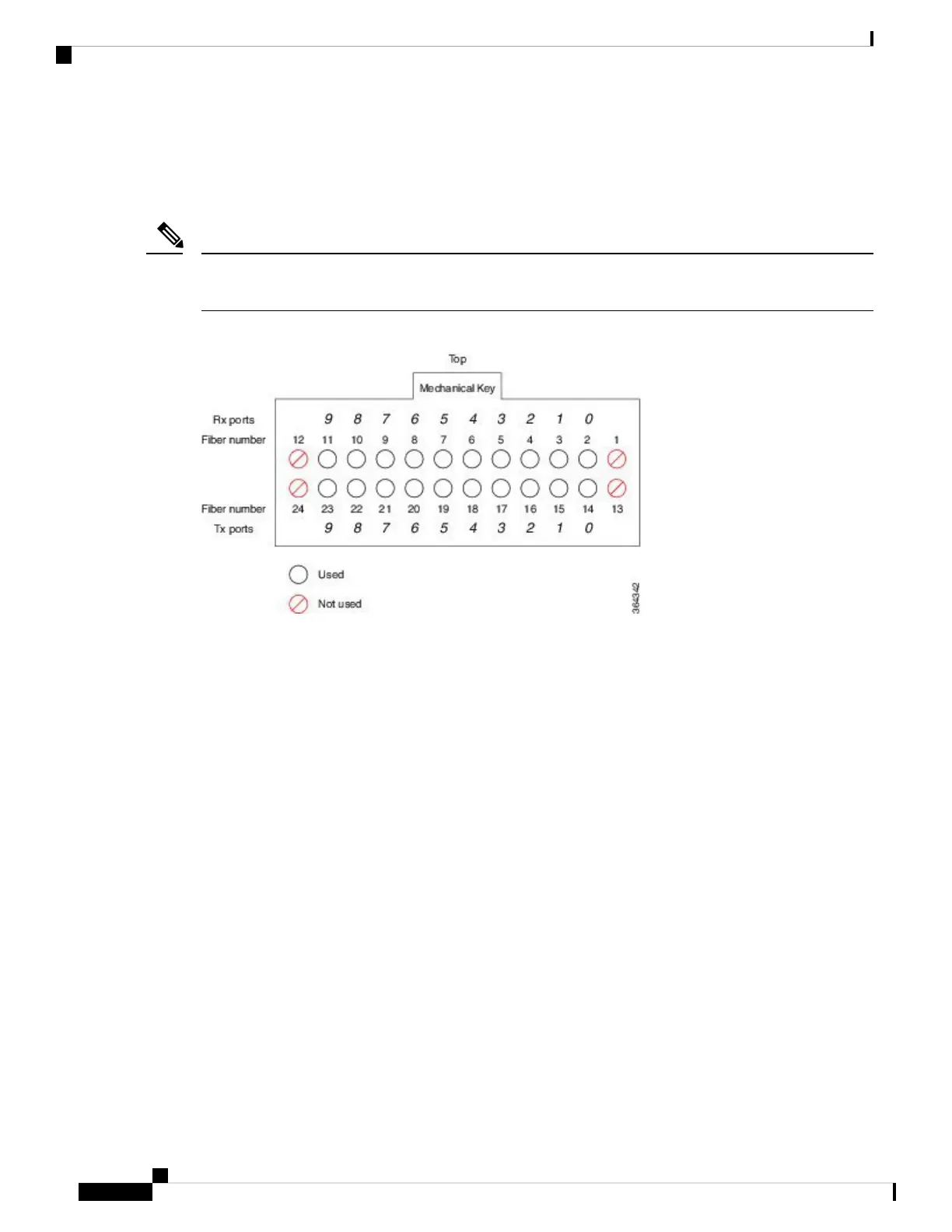
Figure 87: MPO-24 100-Gigabit Connector Pinouts
Looking into the receptacle of the CPAK module with the mechanical key on top, the fibers are numbered as
follows:
• Top row, left to right: Fibers are numbered 12 through 1. Fibers 11, 10, 9, 8, 7, 6, 5, 4, 3, 2 are used for
the optical Rx signals (Channel 9 through 0).
• Bottom row, left to right: Fibers are numbered 24 through 13. Fibers 23, 22, 21, 20, 19, 18, 17, 16, 15,
and 14 are used for the optical Tx signals
Cisco ASR 9000 Series Aggregation Services Router Ethernet Line Card Installation Guide
152
Technical Specifications
MPO-24 Connector Pin Specifications
 Loading...


