——7F24MPO7
——8F1MPO8
TX0_39F5MPO9
TX0_210F4MPO10
TX0_111F3MPO11
TX0_012F2MPO12
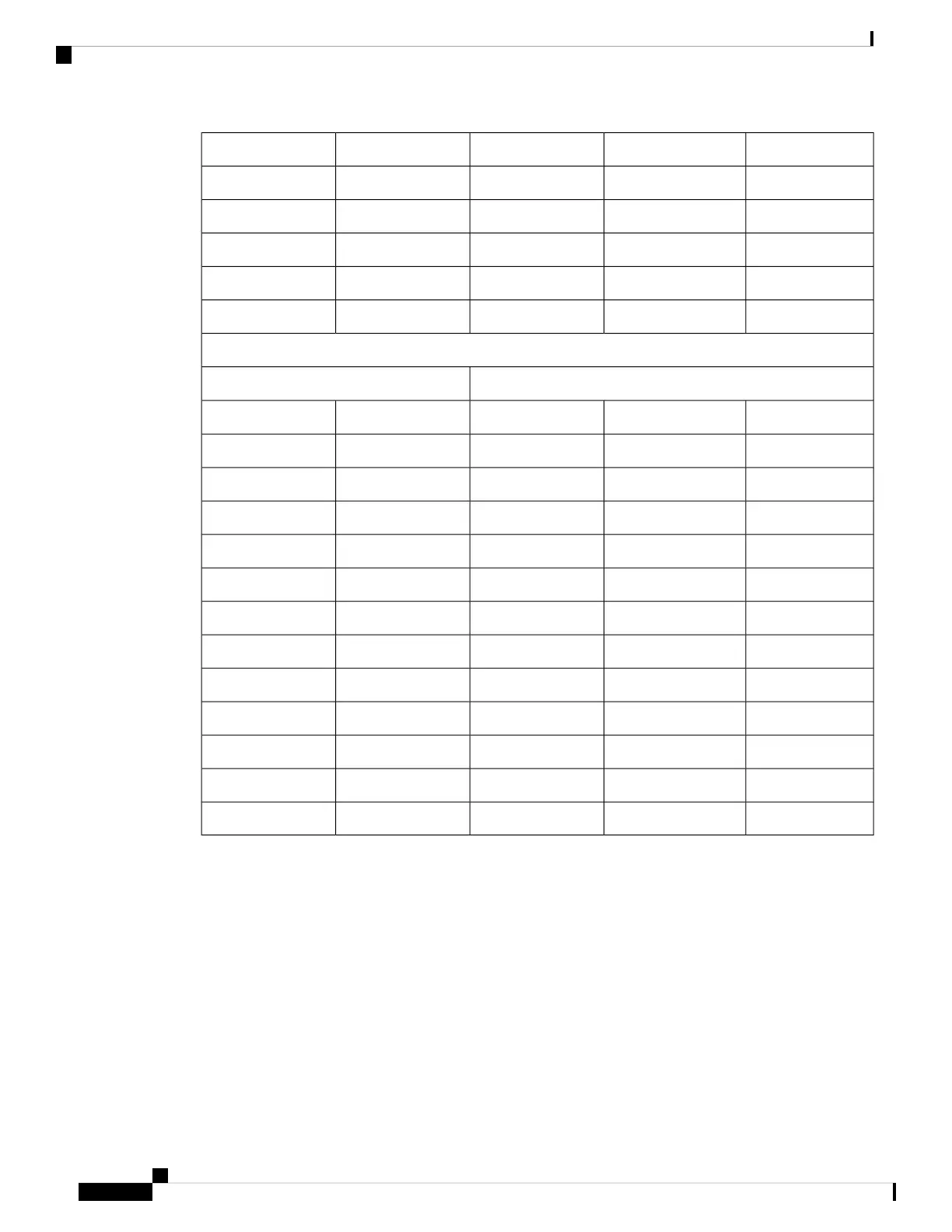
40 G Interface 1
Module Receptacle
Connector
TX/RX40 G Interface_LaneReceptacle Fiber
Fiber IDConnector ID
RX1_01F18MPO1
RX1_12F19MPO2
RX1_23F20MPO3
RX1_34F21MPO4
——5F22MPO5
——6F12MPO6
——7F11MPO7
——8F10MPO8
TX1_39F9MPO9
TX1_210F8MPO10
TX1_111F7MPO11
TX1_012F6MPO12
CPAK-10x10G-LR 2X40 Breakout
The following figure shows the 2X40G breakout for the CPAK-10x10-LR optical module. An MPO-24
APC(angle-polished connector) ribbon fiber breakout to 10x10G LC SM fibers is used at each CPAK. Only
the first 8 fibers are used in this breakout. Two groups of 4 lanes are patched (as needed) to an intermediate
LC patch panel.
The CPAK-10X10G-LR module can only use network interface cables with the angle-polished contact (APC)
face type.
Cisco ASR 9000 Series Aggregation Services Router Ethernet Line Card Installation Guide
156
Technical Specifications
CPAK-10x10G-LR 2X40 Breakout
 Loading...


