0/6/CPU0 A9K-4T-B IOS XR RUN PWR,NSHUT,MON
The node-id appears in the rack/slot/module notation, and the node-id components are as follows:
• rack —In a single-shelf system the rack number is always “0.”
• slot —Number of the physical slot in which the card is installed.
• module —Subslot number of a system hardware component.
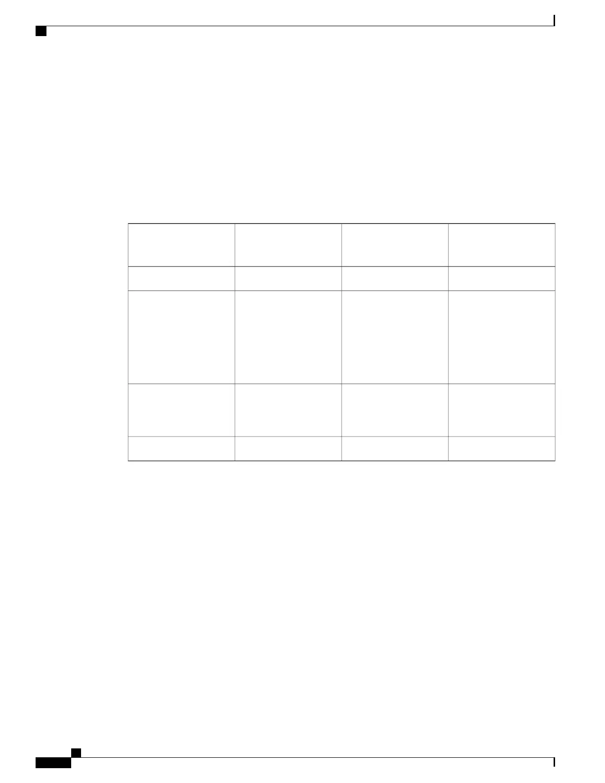
Table 15: Node ID Components, on page 108 summarizes the node-id for each type of card.
Table 15: Node ID Components
Module (the entity on the
card that is the target of
the command)
Slot (the physical slot in
which the card is
installed)
Rack (always “0”)
Card Type (the card to
which your are issuing
commands)
CPU0RSP0 and RSP10Route switch processor
0-X (SFP and XFP
module number on the
line card)
4-7 (6-slot chassis)
0–7 (10-slot chassis)
0-25540-Port Gigabit Ethernet
Line Card
8-Port 10-Gigabit
Ethernet Line Card
4-Port 10-Gigabit
Ethernet Line Card
—
PM0-PM5 (10-slot
chassis)
PM0-PM2 (6-slot chassis
0Power Modules
—FC0–FC1
0Fan controller cards
Displaying Router Node IDs and Status
In administration EXEC mode, the show platform command displays information for all router nodes. In
administration EXEC mode, the command display also includes additional node IDs such as those for fabric
cards, alarm modules, and fan controllers. For each node, this information includes the host card type, the
operational state, and the configuration state. To display information on a single node, enter the command
with a node ID.
The syntax for the show platform command is:
show platform [node-id]
The following example displays the status for all nodes in the system:
RP/0/RSP0/CPU0:router(admin)# show platform
Sat Mar 24 05:02:18.569 DST
Node Type State Config State
-----------------------------------------------------------------------------
Cisco ASR 9000 Series Aggregation Services Router System Management Configuration Guide, Release 5.1.x
108
Managing the Router Hardware
Displaying Router Node IDs and Status
 Loading...


