Engine
Installing Rotor to Crankshaft.
1.
Inspect tapered portion of crankshaft for
damage. If small imperfections or burrs
exist clean with a fine file or emery cloth. If
necessary, lap crankshaft and rotor wit
h
180 grit lapping compound.
2.
Clean tapered surfaces of crankshaft and
r
otor with brake parts cleaner or other quick
evaporating cleaner.
3.
Install woodruff key into crankshaft.
Note: Ensure that top of woodruff key is
par
allel with the tapered portion of t
he
cr
ankshaft.
4.
Slide flywheel onto the crankshaft.
5.
Securing flywheel.
•
On 2019+ units install the M22 nut
and torque to 160 Nm.
•
On Prior years slide the fan hub
ag
ainst the rotor. Run a bolt in the
end of the crankshaft and remove 3
x
at
a force not exceeding 70 Nm.
Discard bolt.
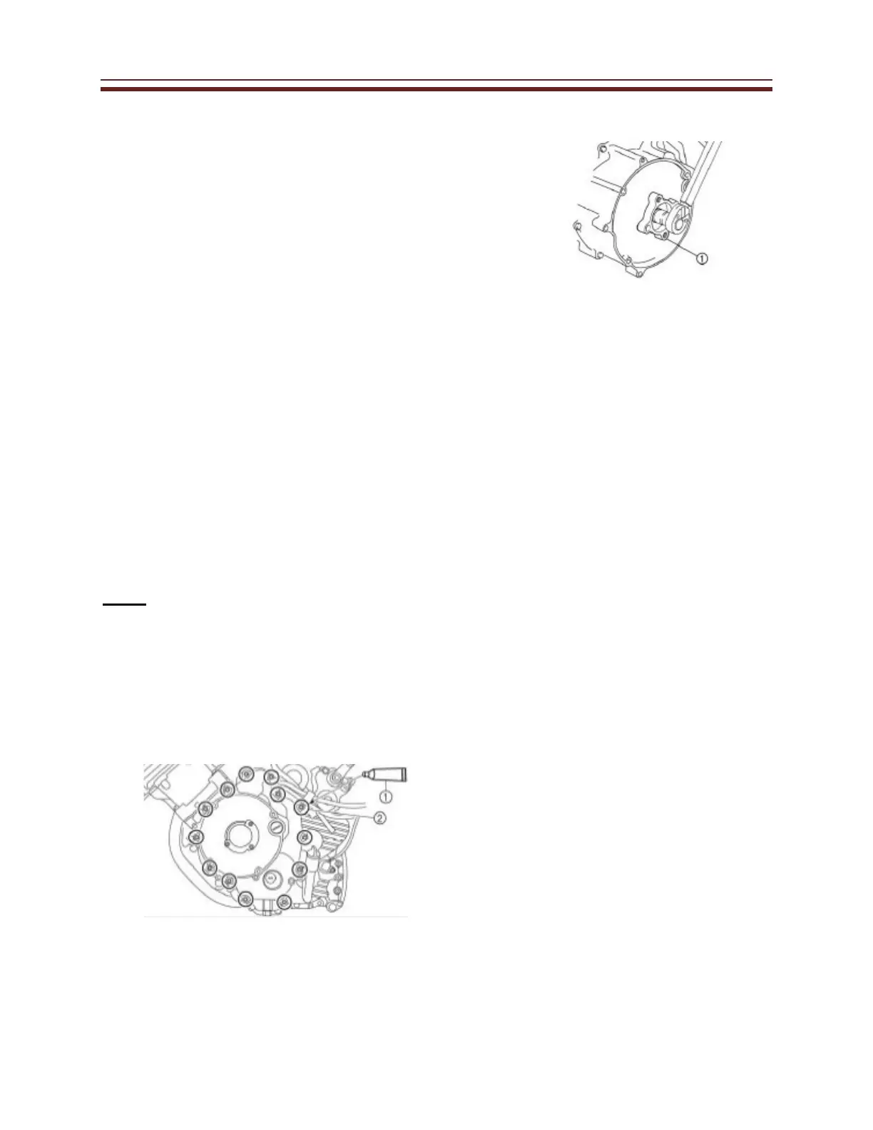
Note:
When installing the A.C. Magneto cover
use a long rod to hold the A.C. Magneto
rotor in position from the outside. This
will make assembly easier. Be careful not
to damage the oil seal. Apply sealant (1)
to the bolt threads (2) shown in this
illustration.
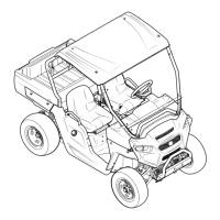
Before installing the engine cooling
fan pulley, do not forget to install the
O-ring.
Install Engine cooling fan Pulley (1)
75 Nm or 55 ft lbs
Note: Do not reuse bolt used to
secure fan hub.
 Loading...