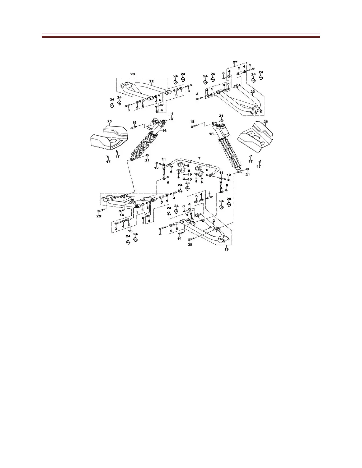
EasyManuals Logo
Home>Cub Cadet>Utility Vehicle>Challenger 550

Cub Cadet Challenger 550 User Manual

Cub Cadet Challenger 550
255 pages
To Next Page IconTo Next Page
To Previous Page IconTo Previous Page
Page #196 background imageLoading...
Page #196 background image
5‐52
Chassis
Rear Suspension and A arm
No.
1
Part Name
Removing the rear suspension
B frame welding kit (rear right)
Qty
1
Remarks
2
B frame welding kit (rear left)
1
3
Bolt hexagon flange head M10×1.25-78
8
4
bushing 23×28
8
5
tube 10.3×23×50
8
6
Nut lock M10×1.25
12
7
Stabilizer bar welding kit(rear)
1
8
Buffer stabilizer bar 20×45
2
9
Strap buffer plate
2
10
Bolt hexagon flange head M8×20
4
11
Rod ball kit (rear)
2
12
Bolt hexagon flange head M10×1.25-45
2
13
B frame kit (rear left) assembly
1
14
Bolt hexagon flange head M10×1.25-40
2

Table of Contents

Questions and Answers:

Question and Answer IconNeed help?

Do you have a question about the Cub Cadet Challenger 550 and is the answer not in the manual?

Cub Cadet Challenger 550 Specifications

General IconGeneral
BrandCub Cadet
ModelChallenger 550
CategoryUtility Vehicle
LanguageEnglish

Related product manuals