Electrical
Checking the switch
Use a pocket tester to check the terminals
for continuity. If the continuity is faulty at
any point, replace the switch.
Note:
•
Set the pocket tester to “0” before
starting the test.
•
The pocket tester should be set to the
“Ω × 1” range when testing the switch
for continuity.
•
Turn the switch on and off a few times
when checking it.
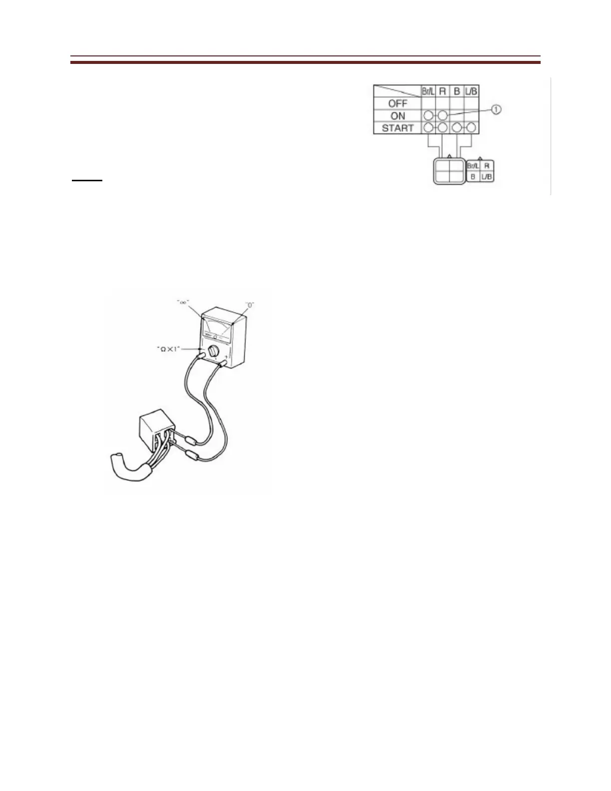
The terminal connections for switches
(main switch, light switch, etc.) are shown
in a chart similar to the one on the left.
This chart shows the switch positions in
the column and the switch lead colors in
the top row.
For each switch position, “ ” indicates the
terminals with continuity.
The example chart shows that:
①There is continuity between the
“Brown/Blue and Red” leads when the
switch is set to “ON”.
 Loading...