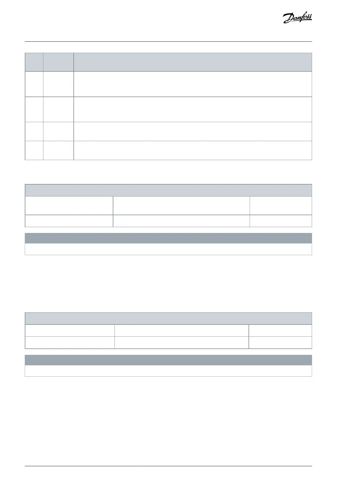
Continuous measurement of distance between master and follower marker. At every follower marker the
distance is measured to the latest master marker. The result of the measurement is updated in parameter
18-24 Marker Pos. Offset in position units as defined in parameter group 17-0* Position Scaling.
Continuous mesaurement of distance between master and follower marker. At every master marker the
distance is measured to the latest follower maker. The result of the measurement is updated in parameter
18-24 Marker Po. Offset in position units as defined in parameter group 17-0* Position Scaling.
Synchronizing according to the profile defined by parameter 3-36 CAM Master Table and parameter 3-37
CAM Follower Table.
Synchronizing according to the profile defined by parameter 3-36 CAM Master Table and parameter 3-37
CAM Follower Table with master offset defined in parameter 3-26 Master Offset.
Parameter 3-34 Marker Distance
Table 216: Parameter 3-34 Marker Distance
Default value: 0 CustomReadoutUnit2
Parameter type: Range, 0 - 2147483647 CustomReadoutU-
nit2
N O T I C E
This parameter is only available with software version 48.XX.
Enter the approximate distance between 2 markers. To measure the marker distance for follower or master marker, select the corre-
sponding marker measuring function in parameter 3-33 Sync. Mode & Start Behavior. Marker distance is in position units as defined in
parameter group 17-1* Position Scaling. The value is converted to the position units of the follower using the master scale set in
parameter 3-22 Master Scale Numerator and parameter 3-23 Master Scale Denominator. Configure the marker distance to utilize the
marker window function.
Parameter 3-35 Marker Window
Table 217: Parameter 3-35 Marker Window
Default value: 0 CustomReadoutUnit2
Parameter type: Range, 0 - par. 3-34 CustomReadoutUnit2
N O T I C E
This parameter is only available with software version 48.XX.
Make sure to configure parameter 3-34 Marker Distance. The marker window function is only active when the marker distance is set.
Enter the window size around the expected marker position where the marker is accepted. The marker window is used for both
master and follower marker and the position units are as defined in parameter group 17-7* Position Scaling. Master position value is
converted to follower position units using the master scale set in parameter 3-22 Master Scale Numerator and parameter 3-23 Master
Scale Denominator.
AU275636650261en-000101 / 130R0334140 | Danfoss A/S © 2022.12
Parameter Descriptions
VLT AutomationDrive FC 301/302
Programming Guide
 Loading...


