Power Controller Cascade multiple Digi RPM units
Digi CM User Guide 128
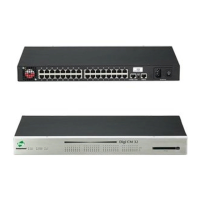
The Power controller statistics screen appears to show the Alarm threshold, Current temp, Circuit
breaker condition, RMS voltage, RMS current, and Max current detected.
The Clear button will reset the Max current detected to 0.0 amps. From this screen click Outlets.
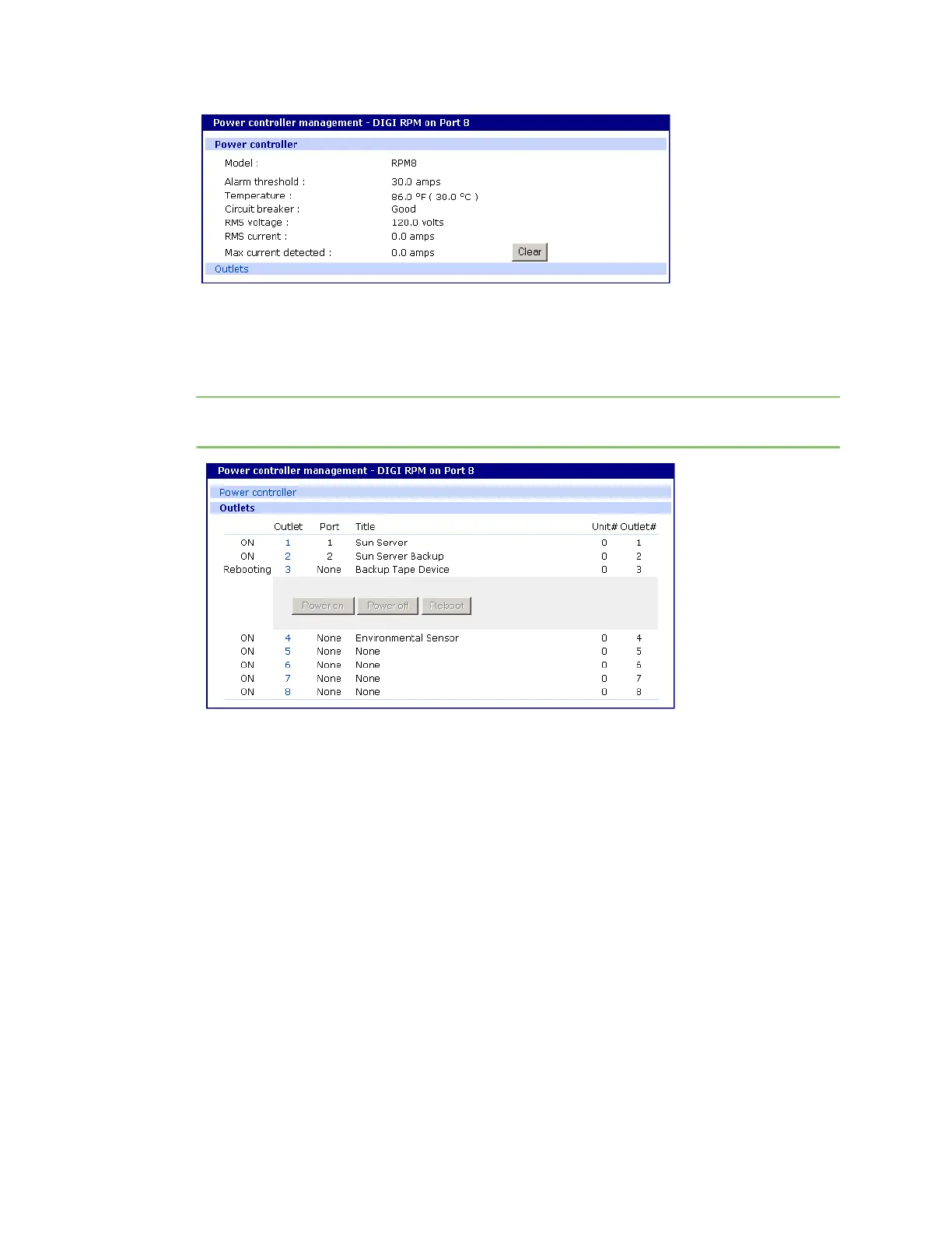
1 Select the outlet number that you would like to manage.
Note The screen below shows that all the outlets are powered On and outlet 3 is Rebooting,
therefore the Backup Tape Device is power cycling.
2 Click Power on, Power off, or Reboot depending on what you want the outlet to do.
Cascade multiple Digi RPM units
The Digi RPM power controllers can be cascaded when used with the Digi CM unit.
The DIP switches on the front panel of the Digi RPM allow configuring unique identities (ID) to the
Digi RPMs so they can be identified. In a cascaded environment each unit has to be configured to a
unique ID.
To cascade the Digi RPM units, connect a serial port of the Digi CM unit to the Console Port of the
first Digi RPM unit using a straight-thru cable. Connect the “Cascade” Port of the first Digi RPM unit
to the “Console” Port of the second.
Following an example of two cascaded Digi RPM units connected to a Digi CM unit.S
Please note that the ID for the first unit is set to 0 and for the second unit it is set to 1.
 Loading...