G3 Series EtherCAT
TM
Technical Manual
15-169
Subject to change without notice
www.asco.com/g3
Bit Mapping Rules
The bit mapping for a G3 manifold varies with the physical configuration of the manifold. The following is a breakdown
of the bit mapping rules associated with the Aventics valve manifold.
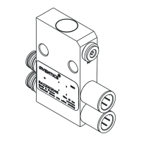
Valve Side
1) Solenoid coil outputs are connected to the valve coils using the Z-Boards
™
.
2) The valve solenoid coil output portion of the total output size is fixed at 4 bytes.
3) Solenoid coil output addressing begins at the 1
st
manifold station nearest the node using “14” coil 1
st
and then, if
applicable, the “12” coil, and continues in ascending order away from the communication node.
4) Each manifold station allocates 1 or 2 output bits. This is dependent on the Z-Board
™
type installed.
A single Z-Board
™
allocates 1 output bit. A double Z-Board
™
allocates 2 output bits.
5) Z-Boards
™
can be used in any arrangement (all singles, all doubles, or any combination) as long as output group
No.1 and output group No. 2 bits do not overlap (i.e. combinations of Z-Boards
™
could exist where the physical
configuration of the manifold could exceed the output capacity.
Discrete I/O Side
Outputs
1) The Sub-Bus output byte size portion is self-configuring in byte increments, after an output module is installed on
the Sub-Bus and power is applied.
2) Outputs are mapped consecutively by module. The output bits from the 1
st
module will be mapped directly after
the bits from the valve coils. The output bits from the second module will be mapped directly after the output bits
from the 1
st
module and so on.
Inputs
1) The Sub-Bus input byte size portion is self-configuring in byte increments, after an input module is plugged into
back plane and power is applied.
2) Inputs are mapped consecutively by module. The input bits from the 1
st
module will be mapped directly after the
status bits from the valve side. The input bits from the second module will be mapped directly after the input
bits from the 1
st
module and so on.
3) All of the modules have associated internal status bits, which will affect the total value of input bytes.
4) When a module has discrete and status inputs, the status bits are mapped after the discrete input bits.
Single solenoid valves can be used with double Z-Boards
TM
. However, one of the
two available outputs will remain unused.
 Loading...