G3 Series EtherCAT
TM
Technical Manual
7-61
Subject to change without notice
www.asco.com/g3
G3 Sub-Bus Field Wiring Directions
The purpose of this document is to instruct the end user
of the proper wiring techniques required to make a
G3 Sub-Bus cable from the available bulk cable and field wireable
ends. The effectiveness of the resultant assembly remains
on the end user and may have bearing on the proper functionality
of the G3 Sub-Bus operation; please follow the manufacturer’s
Cable Assembly Procedure properly.
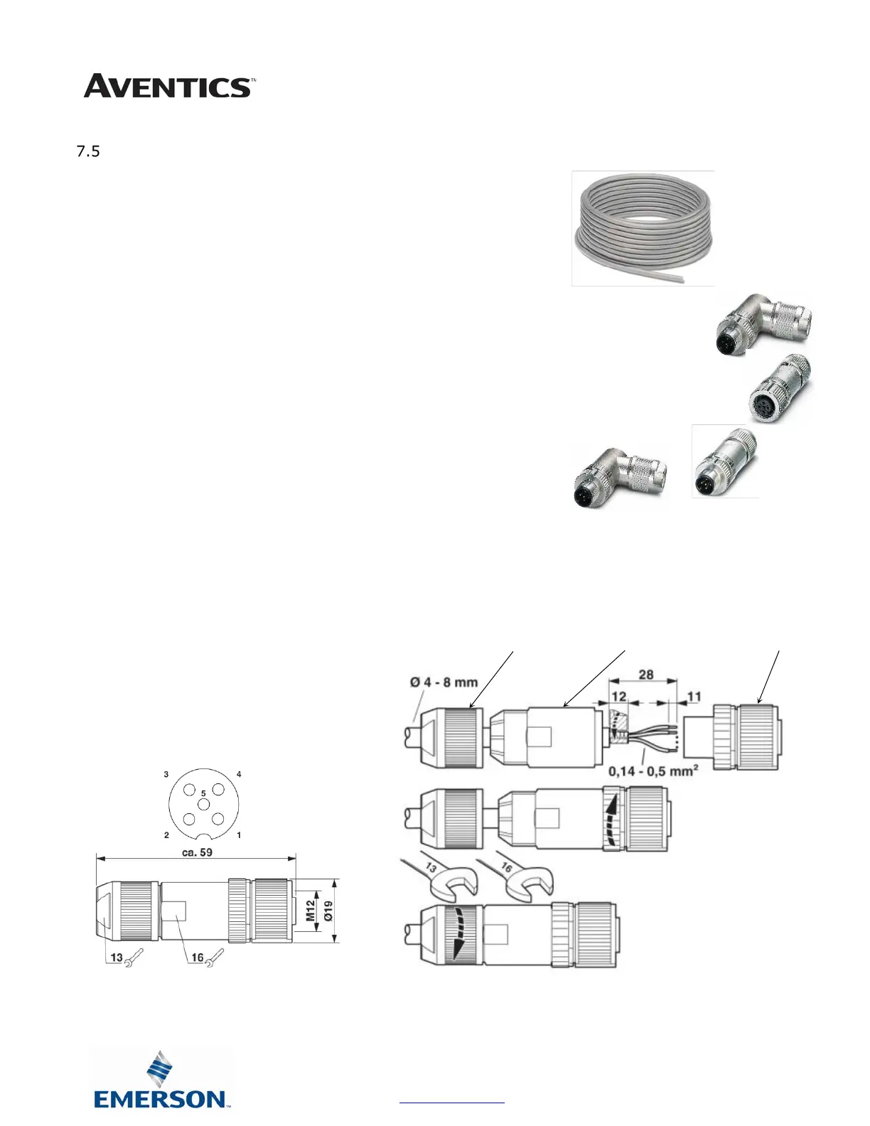
Cable Assembly Procedure
Step No.1 Cut cable to desired length.
Step No.2 Run cable through Pressure Nut and Housing.
Step No.3 Strip cable jacket back 28mm (1.10”) for straight
connectors and 35mm (1.38”) for 90° connectors.
Step No.4 Remove shielding from end of wires back
approximately 16mm (.630”).
Step No.5 Apply shielding foil provided, around the shortened
end of the shielding.
Step No.6 Strip individual conductors back approximately 11mm (.433”).
Step No.7 Push stranded wires into appropriate colored terminal.
Step No.8 Attach the connector body onto the housing and tighten.
Step No.9 Attach the pressure nut on the back side and tighten
Step No.10 Confirm Continuity between all pins.
1 = Shield Wire (must be connected)
2 = Red
3 = Black
4 = White
5 = Blue
 Loading...