G3 Series EtherCAT
TM
Technical Manual
16-180
Subject to change without notice
www.asco.com/g3
Appendix
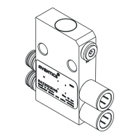
System Specifications
Supply Voltage
Valves (2005, 2012, 2035): 24 VDC + 10%, -15%
Valves (501, 502, 503): 24 VDC +/- 10%
Node and Discrete I/O: 24 VDC ± 10%
Current
Total current on the Auxiliary Power Connector (“Valves and Outputs” and
“Node and Inputs” Pins) must not exceed 8 Amps.
Internal Electronic
Resettable
Fuses
The Auxiliary Power Connector pins are each internally fused with an electronically
resettable fuse. These fuses are set to the maximum current allowable through the G3
electronics.
Recommended
External Fuse
External fuses should be chosen depending upon manifold configuration. Please refer to
power consumption chart on page 4-26 for additional fuse sizing information.
Output spike suppression is internally provided for both discrete and valve outputs.
Discrete Outputs
Maximum 0.5 Amps per output
. All outputs are short circuit protected and have internal
spike suppression. Contact factory for higher current requirements.
Valve
Drivers
Maximum 0.5 Amps per output. All output points are short circuit protected and have
internal spike suppression.
Operating Temperature for
Electronic Components
23 to 114°F (-5 to 50°C)
 Loading...