G3 Series EtherCAT
TM
Technical Manual
15-178
Subject to change without notice
www.asco.com/g3
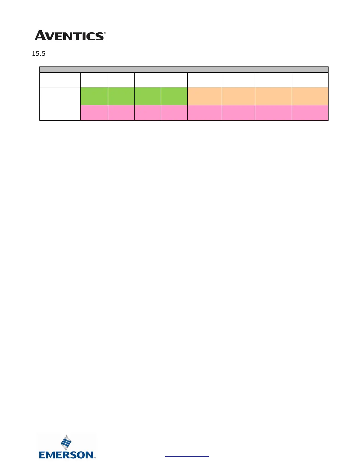
I/O Mapped Diagnostic Word
Byte 0 (Communication Status)
Byte 0, Bit 0 Switched Power Status = Bit is high when valve / output power is not present on the
comm. module.
Byte 0, Bit 1 Un-switched Power Status = Bit is high when node / input power is below 19VDC
Byte 0, Bit 2 Sub-Bus Error = Bit is high when there is an error on the sub-bus; see “Byte 1” of the diagnostic
word for description.
Byte 0, Bit 3 Sub-Bus Short Circuit = A short circuit has been detected across the Sub-Bus
BYTE Bit 7 Bit 6 Bit 5 Bit 4 Bit 3 Bit 2 Bit 1 Bit 0
0
(Comm. Status)
Reserved Reserved Reserved Reserved
Sub-Bus
Short Circuit
(1 = Error)
Sub-Bus
Error
(1=Error)
Un-Switched
Power Status
(1=Error)
Switched
Power Status
(1=Error)
(Sub-Bus
Error
Code
Error
Code
Error
Code
Module
Address
Module
Address
Module
Address
Module
Address
Module
Address
 Loading...